Dynaudio Air Series manual Placing the Subwoofer

Page 28

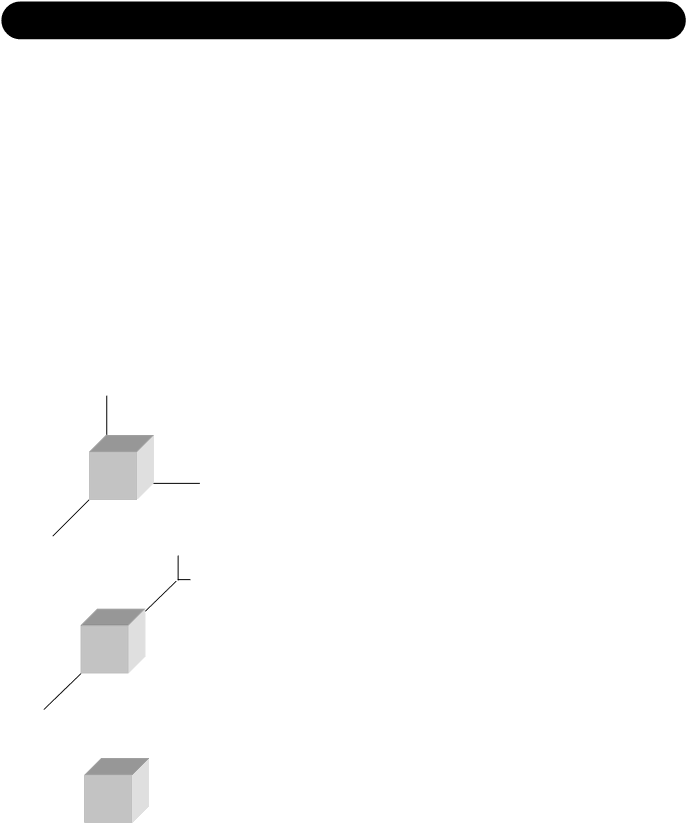
PLACING THE SUBWOOFER

Overview

Placement on the floor

Advantages

Disadvantages


In the corner

Gain of bass response

Excitation of most standing waves in the


room, hence very uneven sound distribution


Adjacent to wall

Gain of bass response

Excitation of several standing waves in the


room, hence very uneven sound distribution


Free standing

Position can be optimized with

It may take up space on the floor


regard to standing waves


Floor standing

The subwoofer is under normal conditions always placed directly on the floor. This is taken into account in the basic design and the basic settings of the AIR system.

Placement in the corner

This is a π/2 radiation, which yields a gain of 18 dB in the frequency range where the monitor is considered to be omni-directional.

Most standing waves have their maximum in the corners of the room. Especially if the room has a cubic or shoebox shape (the room having all walls in parallel). the placement of the subwoofer in the corner may cause uneven sound distribution of the bass.

The corner position is normally only preferred if all opposite surfaces in the room are not in parallel.

Adjacent to a wall

This is a π radiation, which yield a gain of 12 dB in the frequency range where the monitor is considered to be omni-directional.

This position adjacent to a wall is commonly used, and it can be OK, but it must be noticed that the subwoofer should neither be placed in the middle or in the quarter points between two sidewalls if these are in parallel.

(See pages 29-32 for the optimum positions with regard to standing waves.)

Free standing

This is a π radiation, which yield a gain of 6 dB in the frequency range where the monitor is considered to be omni-directional.

The free standing position is highly recommended in all cubic and shoebox shaped rooms.

In any case: Try to avoid placing the woofer on the half or quarter lines between walls.

26

Image 28
Contents Page Page Important Safety Instructions Voltage Line plug according to standardPage Table of Contents Quick Setup Reference Quick Setup Reference Operational Overview Main DisplaySetups Stereo SetupStereo Setup with mono Subs Stereo Setup with stereo SubsDigital Setup Analog SetupThis illustration shows how to connect a 5.1 digital setup This illustration shows how to connect a 5.1 analog setupThis illustration shows how to connect a 5.3 Digital setup This illustration shows how to connect a 5.3 Analog setupThis illustration shows how to connect a 6.1 Analog setup Dig/6 MasterStereo Setup With Chains on L & R Other Chained SetupsAnalog/Digital setup Analog connectionsDigital 192 kHz Digital Setup Introduction This ManualBreak Product ConceptRemote Control Common FeaturesMaster Unit Slave & Sub UnitsRear Panel Description Master Master Unit Analog I/OSlave/Sub Optional Digital I/O cardAIR Display Overload IndicationEnter key Cursor UP/DOWN keys Overload Indication LEDPress Enter to access the Select Mode Parameter DescriptionBasic operation in all menus Main DisplaySetup Menu SetupSet Monitor Task External ClockRecall LFE channel noteStore Placing the Monitors OverviewOn the bridge / Console Close to wall / WallOther situations Checking the placement Phase checkingChecking by ear when listening to the signals In phase EvaluationEqualizing NextCalibrating Main Monitors Curves Interchannel calibrationAcoustic level calibration CurvePlacing the Subwoofer Low frequency sweeps EvaluationChecking summing phase cancellation To CalibrateControlling standing waves Checking the CrosspointPhase Phase IntroductionLFE Gain PolarityGood acoustics AcousticsReverberation time Sabines formula Absorbers DiffusersMembrane absorbers Absorbtion or diffusion ? Resonance absorbersBackground Info Acoustics Standing WavesRoom modes Axial Tangential RadialHow to prohibit standing waves How does the standing waves influence the sound field?Acoustics Background Info Comb Filtering Or + Dip frequenciesRear wall cancellation Subwoofer Background Info SubwooferSubwoofer & LFE Channel Background Info LFE ChannelCross-overs Low Pass LFE GainAcoustic summation of audio signals Delaying Monitors LINE-UP & CalibrationCinema setup LINE-UP & Calibration Background Info How to measure the sound pressure?Calibration of 5.1 in an ITU-775 arrangement AIR Remote Remote Control FeaturesIntroduction Preset 1/3 and 2/4 keys Volume potentiometerREF Level 1-3 keys Shift keyAIR Soft Navigating AIR SoftMain ToolsPreset List NetworkSystem Setup Calibrate AIR-Base Chained monitorsReset Procedures MiscellaneousGlobal Parameters Local ParametersCables TC Link Standard Cat-5 cablesAES/EBU Standard cables Serial to Cat-5 cableAIR 6 & AIR 15 Master and Slave AIR 20 & AIR 25 Master and SlaveAIR-Base-1 & AIR-Base-2 AIR BaseGeneral for all Products Room & DistanceAIR Remote specs Delay in System & Error Messages ETC Error messages etcCertificate Of Conformity Certificate of ConformityAIR AIR-Base Preset List # Name