Emerson AC4 user manual Upload the Configuration File

Page 46

System and Control Options

Upload the Configuration File

13.At the prompt to Initiate an Upload of Configuration File, enter Y (Yes - begin) or N (No - cancel). The current setting appears in brackets—[N] in the following example.

>INITIATE AN UPLOAD OF CONFIGURATION FILE-YES(Y) OR NO(N)? >[N]

>[

NOTE

The following instructions refer to the Microsoft Windows HyperTerminal program. These steps may vary for other communications programs.

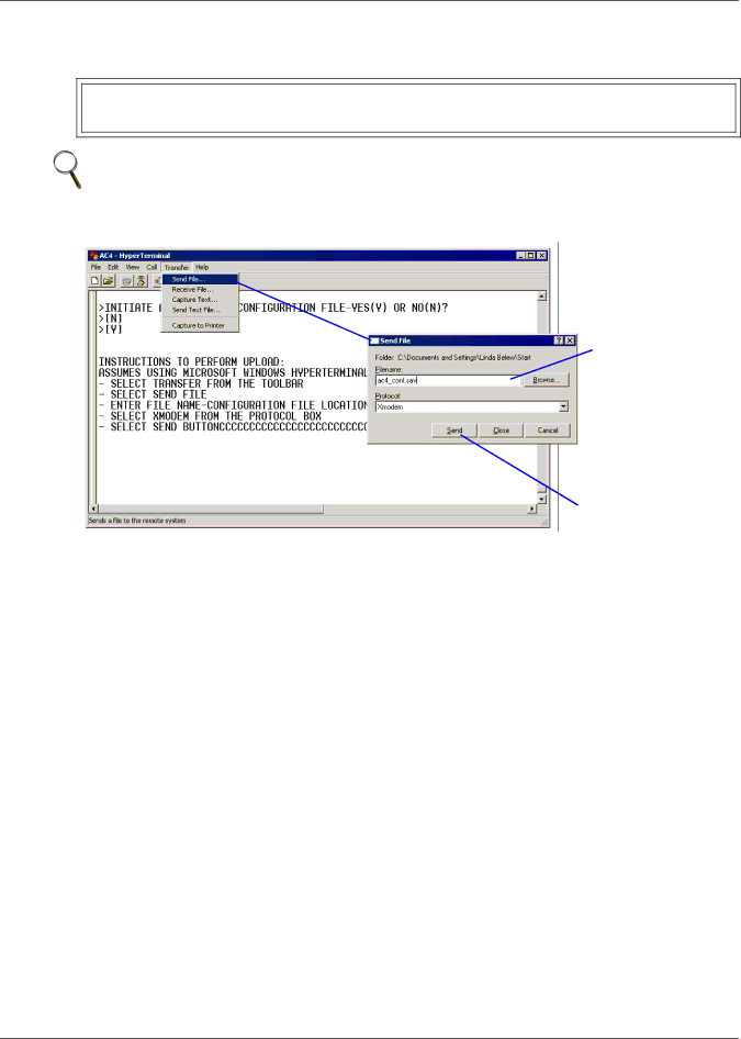
14. At the top of the HyperTerminal window, shown below, click on Transfer, then on Send File.

Enter filename - for example, AC4_CONF.SAV

Select

Xmodem

Send button

15.In the Send File window, as shown above:

In the Filename box, enter the full path of the file to be uploaded—for example, AC4_CONF.SAV—or click on the Browse button to locate the file.

In the Protocol box, select Xmodem from the drop-down list.

Click on the Send button. (To close the window without sending the file, click on Close or Cancel.)

16.When the transfer is complete, a confirmation message—“Upload Successful”—appears in the Service Terminal Interface window and the Liebert AC4 reboots with the new configuration.

Liebert® AC4

40

Image 46
Contents Liebert AC4 Page Table of Contents Setup System Setup Common Alarm 7.5 Setup System Setup Zones Appendix a Service Terminal Interface Setup MenuFigures Data Logs Methods of Viewing and Configuring the Liebert AC4Available Alarms IntroductionOutside Enclosure Overview LCD for configurationOperation Device Liebert Challenger Typical ConfigurationDevice RS232 LiebertLiebert HimodHimod Controller Board Overview Controller board componentsLCD connector ConnectorDIP switch 24VAC powerLED indicators summary LED IndicatorsOutput LEDs Status LEDs Input LEDs Typical Sequence Packing Contents Installation ConsiderationsInstallation Unpacking and Preliminary InspectionRequired tools Surface-Mounting the Liebert AC4Mounting the Panel Flush-Mounting the Liebert AC4 Connect Power to the Liebert AC4 Electrical connections to panelWiring and Connections Wiring SpecificationsWiring specifications Connecting Digital Inputs Connecting Digital Inputs and OutputsConnecting Liebert Precision Cooling Units Numbering keysSetting the Digital Output Jumpers Connecting Digital OutputsDigital output jumper settings Common alarm outputs Connecting Common Alarm OutputsRS232 Connector Serial interface connector RS232/EIA5Overview of Menus Guide to Liebert AC4 functionsMain Menu Overview Opening Screen OverviewLCD Menu Overview View Status Options Clearing Active Alarms View Active AlarmsActive Alarms Active AlarmsAlarm log conditions View Alarm LogAlarm Log Alarm LogEvent log conditions View Event LogEvent Log Event LogViewing Additional Input Data View Input StatusInput Status Digital input statesViewing Additional Output Data View Output StatusOutput Status Digital output statesSilence Alarm & Backup LOG Files Service Terminal Interface Silence Alarm Service Terminal Interface onlyBack Up Log Files Service Terminal Interface only Silence Alarm & Backup Log Files Service Terminal Interface System and Control Options LoginLogin Valid characters for data entrySetup System menu Login ScreenSystem & Control menu Clear Alarms&Logs selected Clear Alarms/Logs menuSetup System Overview Setup System Setup InputsChange Label Name of Input Define Input as Alarmable or EventDefine Input as Normally Open or Normally Closed Delay Time Set Up Alarmable Inputs in Latched or Unlatched ModeSet Up Delay Time Latched / UnlatchedChange to Reset Y or Not Reset N Setup System Setup Common AlarmReset Common Alarm Message if too few devices entered Setup System Setup ZonesSet Up a Zone Message if too many devices enteredSetup System Setup Outputs Define Output as Normally Open or Normally ClosedConfigure Output for Loss of Power Fail-Safe Define Operating or Standby ModeEnable or Disable an Output Device in Alarm Status Set ModeChange the Password Setup System Setup System InfoChange Password Reset Password to the Factory Default AaaaSet Date & Time/Automatic Daylight Saving Time Setup Site IDSetup Site ID Set Date & TimeBackup and Upload Configuration File Back Up the Configuration File Upload the Configuration File Factory Defaults Factory DefaultsFirmware Update Service Terminal Interface only Perform Firmware UPDATE-YESY or NON? N Setup Operation Menu Setup OperationSelect Setup Operation Default settings operation featuresSet Interval & Start Time 1- to 99-Day Interval Turn Automatic Sequencing On or OffActivate / Deactivate Set Start Time Hour IntervalSpecify Failed Standby Response Turn Standby Testing On or OffChange Standby Testing Failed Standby responseRestart Delay Time Specify Hold Delay TimeHold Delay Time Setup Operation MenuOverride Output Clear the Alarm Log Clear Alarms & LogsClear Active Alarms Clear the Event LogLiebert AC4 Specifications SpecificationsSpecifications Liebert AC4 Appendix a Service Terminal Interface Comparison of Functions LCD and Service Terminal InterfaceConnecting to the Service Terminal Interface Create a Connection COM1 Port SetupSpecify COM Port Connection Settings tab Properties SetupAscii Setup Ascii Setup buttonConnect to the Service Terminal Interface Click on the file name for example, AC4.htView Status Overview Silence Alarm and Backup Log FilesSetup Menu Overview Main Menu For sample screens, seeView Status Menus View Active AlarmsView Active Alarms Main MenuView Alarm Log View Alarm LogView Event Log View Event LogView Input Status View Input StatusView Output Status View Output StatusSilence Alarm Section A.5.1 Section A.5.2Backup Log Files Event Log File Back Up Alarm Log FileBackup Log Files Alarm Log File Back Up Event Log FileLogin Menu Setup MenuLogin Tips on Using the Service Terminal Interface Setup MenuSetup Menu See DescriptionSetup Inputs Setup InputsSetup Common Alarm Setup Common AlarmSetup Zones Setup ZonesSetup Outputs Setup OutputsSetup System Info Setup System InfoChange Password Setup Site ID Set Date & TimeBackup & Upload Configuration File Backup Backup & Upload Configuration File Upload Factory DefaultsFirmware Update Service Terminal Interface only Firmware UpdateSetup Operation Auto Sequencing Setup OperationAuto Sequencing Standby Testing Setup Operation Standby TestingSetup Operation Hold Delay Hold DelaySetup Operation Failed Standby Failed StandbyOverride Output Restart DelaySetup Operation Restart Delay Override OutputClear Alarms & Logs Clear Active Alarms Clear Alarms & LogsClear Alarms & Logs Clear the Alarm Log Clear Alarms & Logs Clear the Event Log Specifications Liebert AC4 Specifications Specifications Liebert AC4 Page Twor k Ne tIs t Care