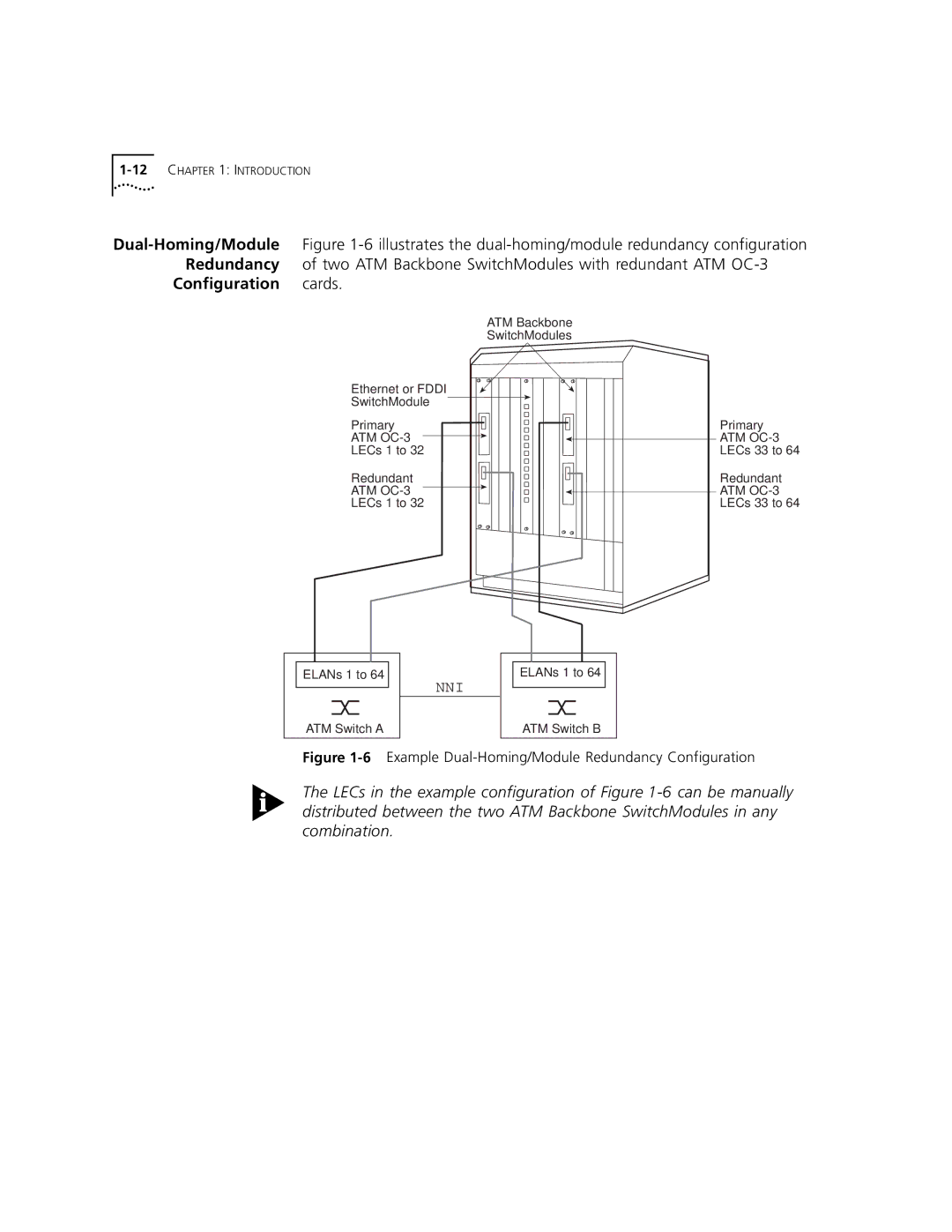
Configuration cards.
| ATM Backbone |
| SwitchModules |
Ethernet or FDDI |
|
SwitchModule |
|
Primary | Primary |
ATM | ATM |
LECs 1 to 32 | LECs 33 to 64 |
Redundant | Redundant |
ATM | ATM |
LECs 1 to 32 | LECs 33 to 64 |
ELANs 1 to 64 | ELANs 1 to 64 |
| NNI |
ATM Switch A | ATM Switch B |
Figure 1-6 Example Dual-Homing/Module Redundancy Configuration
The LECs in the example configuration of Figure