Troubleshooting Using LEDs
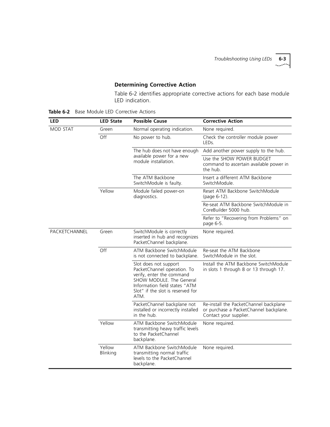
Determining Corrective Action
Table
LED indication.
Table
LED | LED State | Possible Cause | Corrective Action |
|
|
|
|
MOD STAT | Green | Normal operating indication. | None required. |
|
|
|
|
| Off | No power to hub. | Check the controller module power |
|
|
| LEDs. |
The hub does not have enough available power for a new module installation.
Add another power supply to the hub.
Use the SHOW POWER BUDGET command to ascertain available power in the hub.
|
| The ATM Backbone | Insert a different ATM Backbone |
|
| SwitchModule is faulty. | SwitchModule. |
|
|
|
|
| Yellow | Module failed | Reset ATM Backbone SwitchModule |
|
| diagnostics. | (page |
|
|
|
|
|
|
| |
|
|
| CoreBuilder 5000 hub. |
|
|
|
|
|
|
| Refer to “Recovering from Problems” on |
|
|
| page |
|
|
|
|
PACKETCHANNEL | Green | SwitchModule is correctly | None required. |
|
| inserted in hub and recognizes |
|
|
| PacketChannel backplane. |
|
|
|
|
|
| Off | ATM Backbone SwitchModule | |
|
| is not connected to backplane. | SwitchModule in the slot. |
Slot does not support PacketChannel operation. To verify, enter the command SHOW MODULE. The General Information field states “ATM Slot” if the slot is reserved for ATM.
Install the ATM Backbone SwitchModule in slots 1 through 8 or 13 through 17.
PacketChannel backplane not installed or incorrectly installed in the hub.
| Yellow | ATM Backbone SwitchModule | None required. |
|
| transmitting heavy traffic levels |
|
|
| to the PacketChannel |
|
|
| backplane. |
|
|
|
|
|
| Yellow | ATM Backbone SwitchModule | None required. |
| Blinking | transmitting normal traffic |
|
|
| levels to the PacketChannel |
|
|
| backplane. |
|
|
|
|
|