Device Usage box and make sure “Disable in this hardware profile” is not selected. (Windows 95 OEM SR2 and Windows 98 only). Make a note of the COM port and IRQ the modem is using.
Errors reported in the Device Status box generally refer to conflicts. Click the Re- sources tab and read the “Conflicting Device List.” If a conflict is present, click to deselect “Use automatic Setting” and select a configuration that does not cause con- flicts. Manually change the address and IRQ settings if needed. (Refer to Windows 95
Step 3: Modem Diagnostics.
In Control Panel
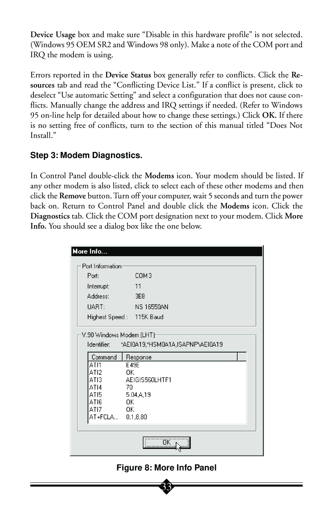
Figure 8: More Info Panel
33