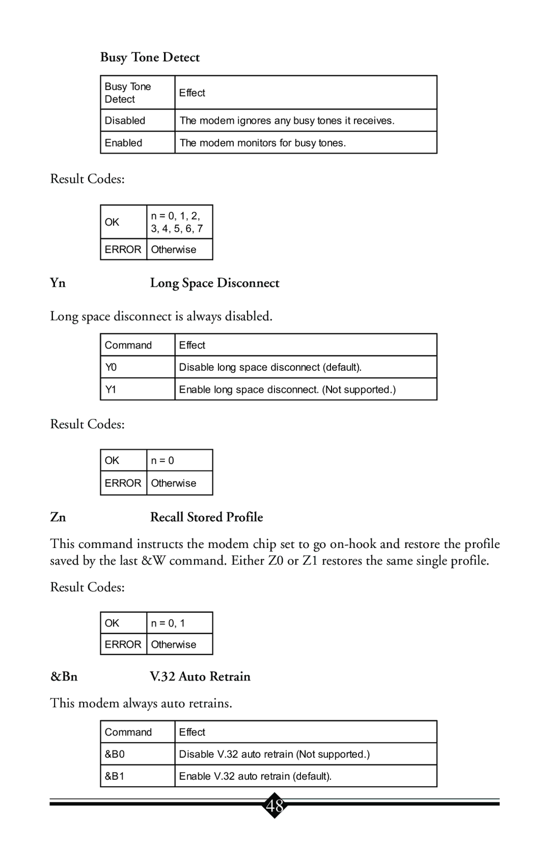
V.90 Internal Voice/Fax Windows Modem
Users Manual
Proprietary Notice and Disclaimer
Table of Contents
Installing The Modem
Installing and Configuring Communications Software
Introduction
Contacting Actiontec Customer Support
Actiontec Electronics, Inc
Phone
For Windows 95 and Windows 98 Installations
Do This First
Figure 1 The Modems Properties Panel
Figure 2 Windows 95 IRQ Resources Dialog Box
Figure 3a COM2 Properties Dialog Box
Figure 3b Windows 95 or 95A COM2 Disable Panel
For Windows NT 4.0 Installation
Fig. 4 Devices Window
Installing The Modem
Hardware Installation
Figure 5 Removing the Backplate
Figure 6 Installing The Modem
Connecting Devices To The Modem
Fig.7 Connecting Devices
Configuring Windows
Page
Page
Configuring Windows 95 OEM SR2
Finish
Page
Page
Page
Next
Configuring Windows
Page
Page
Page
Page
Page
Your modem is now installed and configured for use with Windows
Configuring Windows NT
Page
Step 7 Restart your computer
Step 11 Click Continue to finish the installation
Installing and Configuring Communications Software
The Modem’s Voice Features
AT&F&C1&D2W2
Page
Troubleshooting
Windows 95 and Windows
Step 1 Check System Resources
Step 2 Check Modem Properties
Step 3 Modem Diagnostics
Figure 8 More Info Panel
Step 4 Does Not Install
Uninstalling the Modem
Note to users of Windows 95 and
Note to users of Windows NT
Common Problems
No Dialtone Error
Nothing Appears On The Screen When I Type
Communications Software Does Not Work
when the modem is in use. This includes extension phones, answering machines, cordless phone bases, caller ID boxes and their cables. This reduces the load on your phone line and keeps signal attenuation to a minimum
Appendix A AT Command Set
AT Commands
Repeat Last Command
Answer Command
Communication Standard Setting
Carrier Control
DnDial
Echo Command
Online Data Character Echo Command
Hook Control
Monitor Speaker Volume
Request ID Information
Returns default speed and controller firmware version
Calculates ROM checksum and displays it on the DTE
Modulation Handshake
Monitor Speaker Mode
Return On-line to Data Mode
Select Pulse Dialing
Result Code Control
Select Tone Dialing
VnDCE Response Format
Result Code Option
Extended Result Codes
Dial Tone Detect
Result Code Selection and Call Progress Monitoring
Busy Tone Detect
Long Space Disconnect
Recall Stored Profile
V.32 Auto Retrain
Data Carrier Detect DCD Control
DTR Control
DCD turns on when the remote modem’s carrier signal
mode, the modem disconnects default. If this signal is
V.22bis Guard Tone Control
Auxiliary Relay option
Load Factory Settings
Local Flow Control Selection
Asynchronous Communications Mode
Pulse Dial Make-to-Break Ratio Selection
n = 0, 1
Data Set Ready DSR Option
V.42 or MNP error control mode. If neither error control
Asynchronous Communications Mode
This command is used to display the active profiles
View Active Configuration and Stored Profile
Below is an example of a possible output
Store Current Configuration
Select Stored Profile for Hard Reset
Zn=x
Store Telephone Number
Select Maximum MNP Block Size
Transmit Break to Remote
Adjust Bits/s Rate Control
Modem Port Flow Control
Break Control
Result Codes
Error Control Mode Selection
connect in MNP 2-4 error control procedure. If this fails
V.42, MNP, or buffer default. The modem attempts to
Local Flow Control Selection
Ring indicator signal off after the telephone call is answered
Compatibility command
Inactivity Timer
Protocol Result Code
XON/XOFF Pass Through
Data Calling Tone
V90=x V.90 Downstream Rate and Control
View Numbers in Blacklist
Enable/Disable Data Compression
AT Commands for Testing and Debugging
Write to/Read from DSP Register
Line-to-Line Loopback
ATI11
Self-Test Commands
Description
S-Registers Reference
Command Line Termination Character user defined
Command Line Editing Character user defined
Ring Counter
AT Escape Character user defined
Connection Completion Time-Out
Comma Dial Modifier Time
Wait Before Dialing
Automatic Disconnect Delay
DTMF Dialing Speed
Escape Guard Time
General Bit Mapped Options Status
Timer to Control Sleep Mode
V.34 Modulation Enable/Disable
Inactivity Timer
Synthetic Ring Volume
Data Calling Tone
Dial Line Rate default
56K Dial Line Rate default
Negotiation Fallback default
Auto Rate default 1, range
Auto Mode default 1, range
LAPM Error Control and Feature Negotiation default
ETC Startup Autorating default 0, range
Timer to Control Sleep Mode
Direct Connect Transmit Level default
Local Phone Status
Line Transmit Level
Modem lost carrier signal, or does not detect carrier
The Result Code Summary
Result Code
Description
V42bis-V.42 error control and V.42bis data compression
Appendix B Communications Regulations
FCC Regulations
FCC Part 68 Requirements
Declaration of Conformity
Canadian Department Of Communications CDOC