Chapter 3: Provisioning |
|
|
|
| September 25, 2006 | |||
|
|
|
|
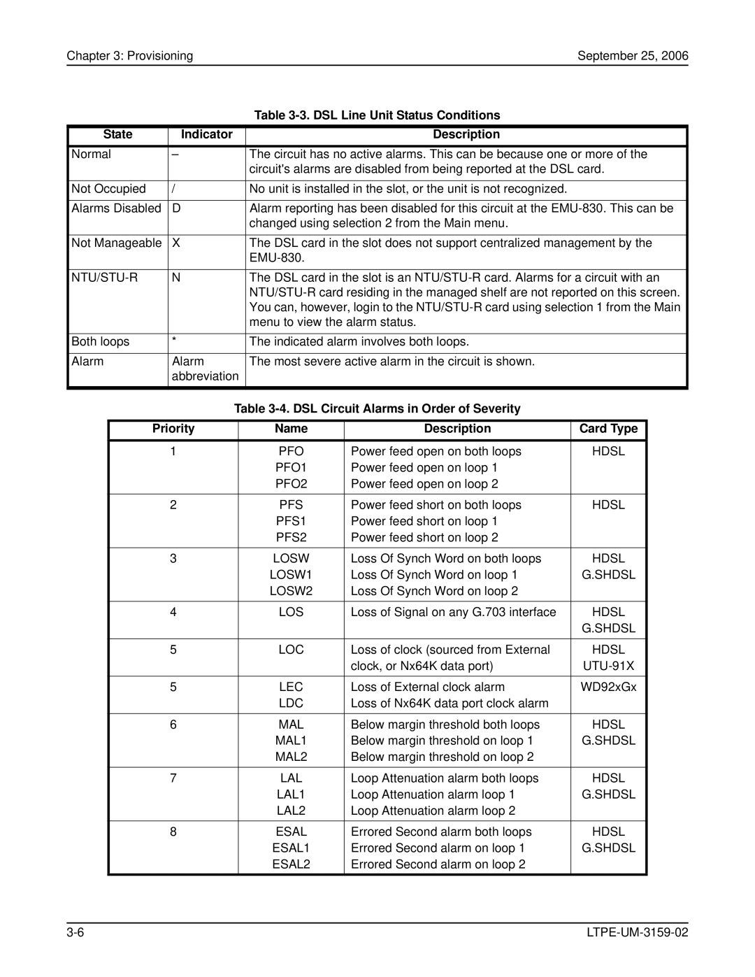
| Table |
|
| |
|
|
|
|
|
|
|
|
|
State | Indicator |
|
|
| Description |
|
| |
Normal | – |
|
| The circuit has no active alarms. This can be because one or more of the | ||||
|
|
|
|
| circuit's alarms are disabled from being reported at the DSL card. | |||
|
|
|
|
|
|
|
|
|
Not Occupied | / |
|
| No unit is installed in the slot, or the unit is not recognized. |
|
| ||
|
|
|
|
|
|
|
|
|
Alarms Disabled | D |
|
| Alarm reporting has been disabled for this circuit at the | ||||
|
|
|
|
| changed using selection 2 from the Main menu. |
|
| |
|
|
|
|
|
|
|
|
|
Not Manageable | X |
|
| The DSL card in the slot does not support centralized management by the | ||||
|
|
|
|
|
|
|
| |
|
|
|
|
|
|
|
|
|
| N |
|
| The DSL card in the slot is an | ||||
|
|
|
|
| ||||
|
|
|
|
| You can, however, login to the | |||
|
|
|
|
| menu to view the alarm status. |
|
| |
|
|
|
|
|
|
|
|
|
Both loops | * |
|
| The indicated alarm involves both loops. |
|
| ||
|
|
|
|
|
|
|
|
|
Alarm | Alarm |
|
| The most severe active alarm in the circuit is shown. |
|
| ||
|
| abbreviation |
|
|
|
| ||
|
|
| Table |
|
| |||
|
|
|
|
|
|
|
| |
| Priority |
|
| Name | Description | Card Type |
| |
|
| 1 |
|
| PFO | Power feed open on both loops | HDSL |
|
|
|
|
|
| PFO1 | Power feed open on loop 1 |
|
|
|
|
|
|
| PFO2 | Power feed open on loop 2 |
|
|
|
|
|
|
|
|
|
|
|
|
| 2 |
|
| PFS | Power feed short on both loops | HDSL |
|
|
|
|
|
| PFS1 | Power feed short on loop 1 |
|
|
|
|
|
|
| PFS2 | Power feed short on loop 2 |
|
|
|
|
|
|
|
|
|
|
|
|
| 3 |
|
| LOSW | Loss Of Synch Word on both loops | HDSL |
|
|
|
|
|
| LOSW1 | Loss Of Synch Word on loop 1 | G.SHDSL |
|
|
|
|
|
| LOSW2 | Loss Of Synch Word on loop 2 |
|
|
|
|
|
|
|
|
|
|
|
|
| 4 |
|
| LOS | Loss of Signal on any G.703 interface | HDSL |
|
|
|
|
|
|
|
| G.SHDSL |
|
|
|
|
|
|
|
|
|
|
|
| 5 |
|
| LOC | Loss of clock (sourced from External | HDSL |
|
|
|
|
|
|
| clock, or Nx64K data port) |
| |
|
|
|
|
|
|
|
|
|
|
| 5 |
|
| LEC | Loss of External clock alarm | WD92xGx |
|
|
|
|
|
| LDC | Loss of Nx64K data port clock alarm |
|
|
|
|
|
|
|
|
|
|
|
|
| 6 |
|
| MAL | Below margin threshold both loops | HDSL |
|
|
|
|
|
| MAL1 | Below margin threshold on loop 1 | G.SHDSL |
|
|
|
|
|
| MAL2 | Below margin threshold on loop 2 |
|
|
|
|
|
|
|
|
|
|
|
|
| 7 |
|
| LAL | Loop Attenuation alarm both loops | HDSL |
|
|
|
|
|
| LAL1 | Loop Attenuation alarm loop 1 | G.SHDSL |
|
|
|
|
|
| LAL2 | Loop Attenuation alarm loop 2 |
|
|
|
|
|
|
|
|
|
|
|
|
| 8 |
|
| ESAL | Errored Second alarm both loops | HDSL |
|
|
|
|
|
| ESAL1 | Errored Second alarm on loop 1 | G.SHDSL |
|
|
|
|
|
| ESAL2 | Errored Second alarm on loop 2 |
|
|