September 25, 2006 | Chapter 2: Installation |
Step | Action |
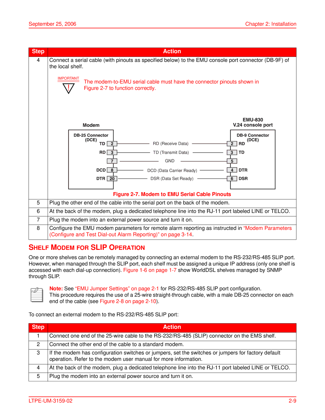
4Connect a serial cable (with pinouts as specified below) to the EMU console port connector
IMPORTANT The
RD (Receive Data)
TD (Transmit Data)
GND
DCD (Data Carrier Ready)
DSR (Data Set Ready)
Figure 2-7. Modem to EMU Serial Cable Pinouts
5Plug the other end of the cable into the serial port on the back of the modem.
6At the back of the modem, plug a dedicated telephone line into the
7Plug the modem into an external power source and turn it on.
8Configure the EMU modem parameters for remote alarm reporting as instructed in “Modem Parameters (Configure and Test
SHELF MODEM FOR SLIP OPERATION
One or more shelves can be remotely managed by connecting an external modem to the
Note: See “EMU Jumper Settings” on page
This procedure requires the use of a
To connect an external modem to the
Step | Action |
1Connect one end of the
2Connect the other end of the cable to a standard modem.
3If the modem has configuration switches or jumpers, set the switches or jumpers for factory default operation. Refer to the modem user manual for more information.
4At the back of the modem, plug a dedicated telephone line into the
5Plug the modem into an external power source and turn it on.