Chapter 2. Installation and Operation
B | F | L | R | V | Z | DD | JJ | NN | ALARM | NC COM NO |
D | J | N | T | X | BB | FF |
| LL |
|
|
A | E | K | P | U | Y | CC | HH | MM |
|
|
C | H | M | S | W | AA | EE |
| KK |
|
|
V.35 INTERFACE | HSSI INTERFACE |
| ||||||||
DTE PORT 4 | DTE PORT 3 | DTE PORT 2 | DTE PORT 1 | |||||||
AUX |
|
|
| DS3 INTERFACE | |
LAN | RX IN | TX OUT |
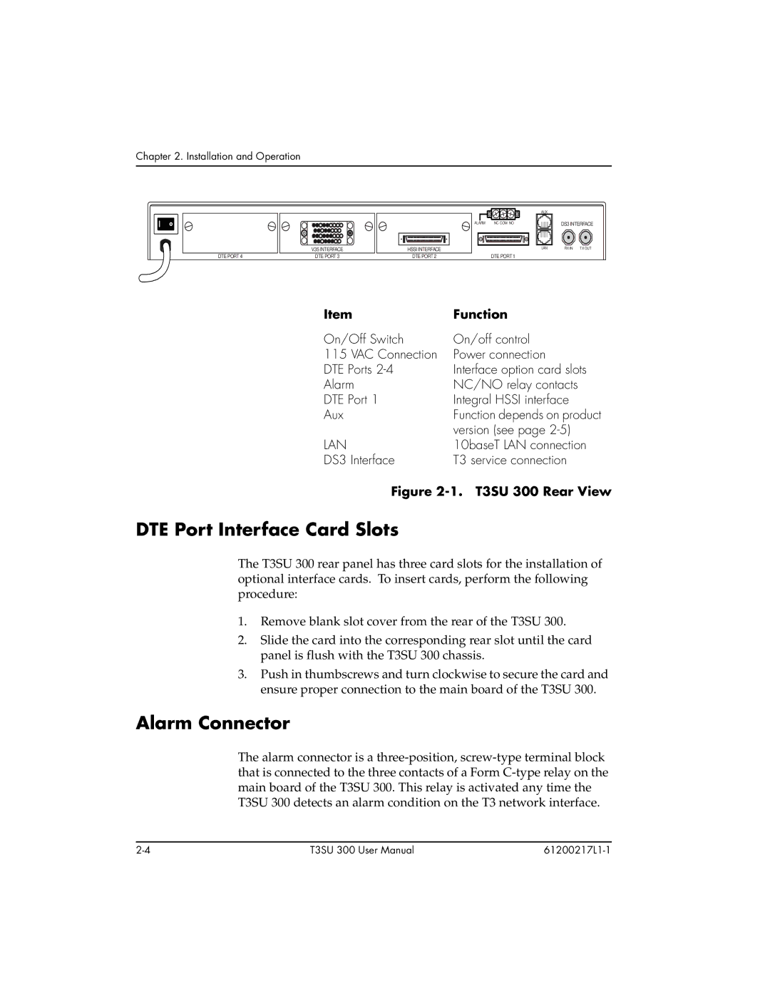
Item | Function |
On/Off Switch | On/off control |
115 VAC Connection | Power connection |
DTE Ports | Interface option card slots |
Alarm | NC/NO relay contacts |
DTE Port 1 | Integral HSSI interface |
Aux | Function depends on product |
| version (see page |
LAN | 10baseT LAN connection |
DS3 Interface | T3 service connection |
Figure 2-1. T3SU 300 Rear View
DTE Port Interface Card Slots
The T3SU 300 rear panel has three card slots for the installation of optional interface cards. To insert cards, perform the following procedure:
1.Remove blank slot cover from the rear of the T3SU 300.
2.Slide the card into the corresponding rear slot until the card panel is flush with the T3SU 300 chassis.
3.Push in thumbscrews and turn clockwise to secure the card and ensure proper connection to the main board of the T3SU 300.
Alarm Connector
The alarm connector is a
T3SU 300 User Manual |