Appendix A Pinouts
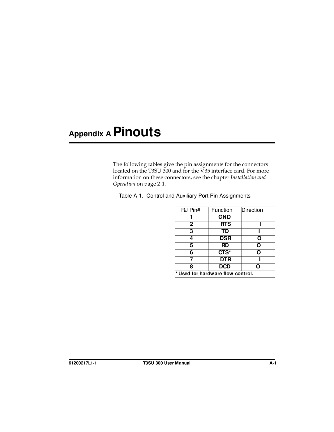
The following tables give the pin assignments for the connectors located on the T3SU 300 and for the V.35 interface card. For more information on these connectors, see the chapter Installation and Operation on page
Table
RJ Pin# | Function | Direction |
1 | GND |
|
2 | RTS | I |
3 | TD | I |
4 | DSR | O |
5 | RD | O |
6 | CTS* | O |
7 | DTR | I |
8 | DCD | O |
*Used for hardware flow control.
T3SU 300 User Manual |