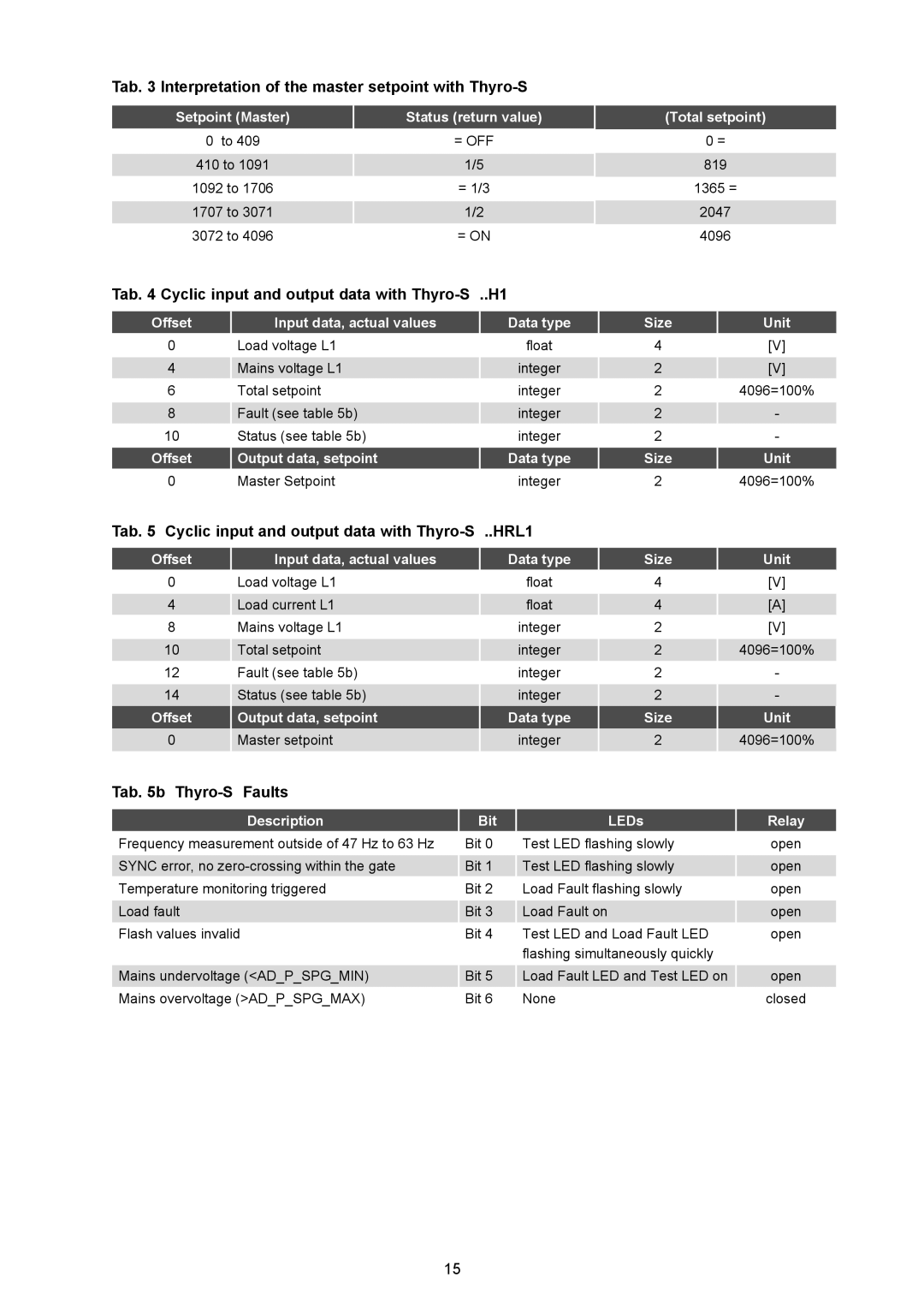
Tab. 3 Interpretation of the master setpoint with Thyro-S
Setpoint (Master) | Status (return value) |
0 to 409 | = OFF |
410 to 1091 | 1/5 |
1092 to 1706 | = 1/3 |
1707 to 3071 | 1/2 |
3072 to 4096 | = ON |
Tab. 4 Cyclic input and output data with Thyro-S ..H1
(Total setpoint)
0=
819
1365 =
2047
4096
Offset | Input data, actual values | Data type | Size | Unit |
0 | Load voltage L1 | float | 4 | [V] |
4 | Mains voltage L1 | integer | 2 | [V] |
6 | Total setpoint | integer | 2 | 4096=100% |
8 | Fault (see table 5b) | integer | 2 | - |
10 | Status (see table 5b) | integer | 2 | - |
Offset | Output data, setpoint | Data type | Size | Unit |
0 | Master Setpoint | integer | 2 | 4096=100% |
Tab. 5 Cyclic input and output data with Thyro-S ..HRL1
Offset | Input data, actual values | Data type | Size | Unit |
0 | Load voltage L1 | float | 4 | [V] |
4 | Load current L1 | float | 4 | [A] |
8 | Mains voltage L1 | integer | 2 | [V] |
10 | Total setpoint | integer | 2 | 4096=100% |
12 | Fault (see table 5b) | integer | 2 | - |
14 | Status (see table 5b) | integer | 2 | - |
Offset | Output data, setpoint | Data type | Size | Unit |
0 | Master setpoint | integer | 2 | 4096=100% |
Tab. 5b Thyro-S Faults
Description | Bit | LEDs | Relay |
Frequency measurement outside of 47 Hz to 63 Hz | Bit 0 | Test LED flashing slowly | open |
SYNC error, no | Bit 1 | Test LED flashing slowly | open |
Temperature monitoring triggered | Bit 2 | Load Fault flashing slowly | open |
Load fault | Bit 3 | Load Fault on | open |
Flash values invalid | Bit 4 | Test LED and Load Fault LED | open |
|
| flashing simultaneously quickly |
|
Mains undervoltage (<AD_P_SPG_MIN) | Bit 5 | Load Fault LED and Test LED on | open |
Mains overvoltage (>AD_P_SPG_MAX) | Bit 6 | None | closed |
15
