Table 2-1. Test Equipment Required (continued)
TYPE | REQUIRED CHARACTERISTICS | USE | RECOMMENDED MODEL |
Switch | SPST, 30A @ 20V | P |
|
DC Power Supply | Voltage range: | T,P | Agilent 6296A |
| Current range: |
|
|
|
|
|
|
Variable Voltage | Range greater than | P,A |
|
Transformer | nominal input AC voltage |
|
|
(autotransformer) | 1KVA |
|
|
|
|
|
|
P = performance | testing A = calibration adjustments | T = troubleshooting | |
*Resistors may be substituted for test where an electronic load is not available.
**Less accurate, and less expensive,
Initial Setup
Maintenance described herein is performed with power supplied to the instrument, and protective covers removed. Such maintenance should be performed only by service trained
personnel who are aware of the hazards involved (for example, fire and electrical shock). Turn off ac power when making or removing connections to the power supply. Where maintenance can be performed without power applied, the power should be
removed.
a.Unplug the line cable and remove the top cover by removing three screws; the rear handle screw and the two
b.Slide the cover to the rear.
c.Plug a control board test connector A2P3 onto the A2J3
d.Turn OVERVOLTAGE ADJUST control A3R59 fully clockwise.
e.Disconnect all loads from output terminals.
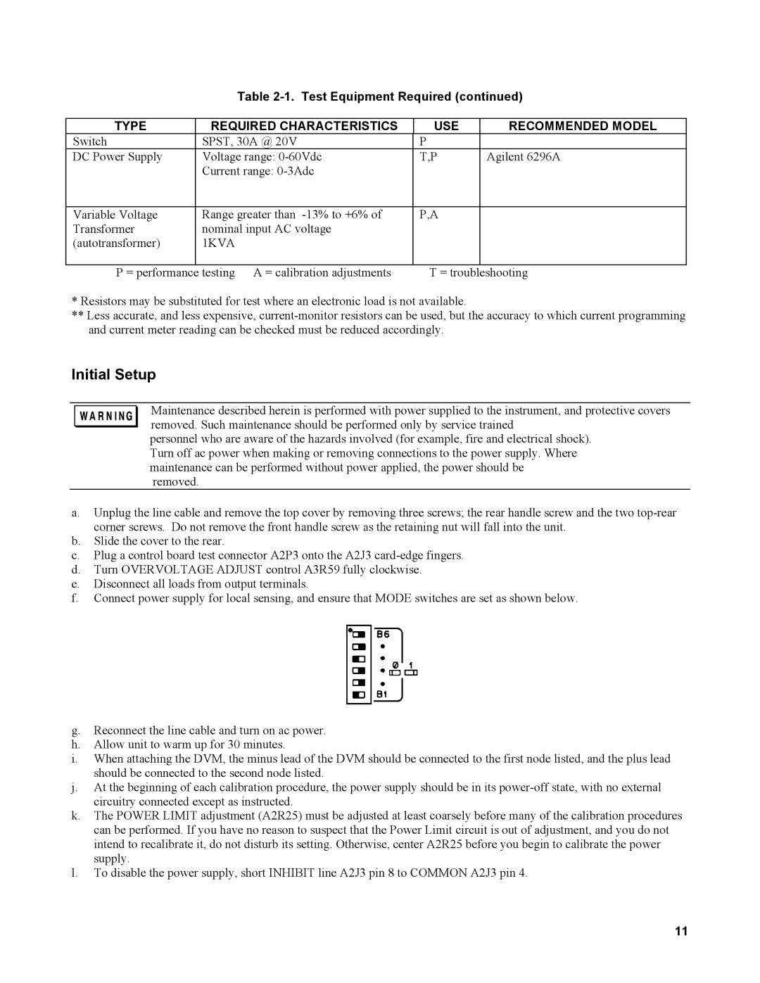
f.Connect power supply for local sensing, and ensure that MODE switches are set as shown below.
g.Reconnect the line cable and turn on ac power.
h.Allow unit to warm up for 30 minutes.
i.When attaching the DVM, the minus lead of the DVM should be connected to the first node listed, and the plus lead should be connected to the second node listed.
j.At the beginning of each calibration procedure, the power supply should be in its
k.The POWER LIMIT adjustment (A2R25) must be adjusted at least coarsely before many of the calibration procedures can be performed. If you have no reason to suspect that the Power Limit circuit is out of adjustment, and you do not intend to recalibrate it, do not disturb its setting. Otherwise, center A2R25 before you begin to calibrate the power supply.
l.To disable the power supply, short INHIBIT line A2J3 pin 8 to COMMON A2J3 pin 4.
11