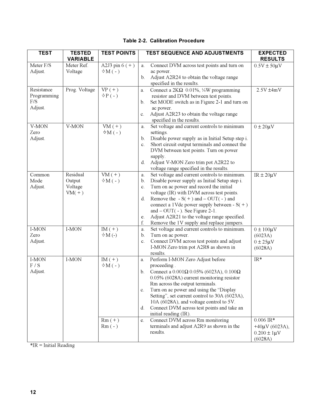
Table 2-2. Calibration Procedure
TEST | TESTED | TEST POINTS |
| TEST SEQUENCE AND ADJUSTMENTS |
| EXPECTED | ||||
| VARIABLE |
|
|
|
| RESULTS | ||||
Meter F/S | Meter Ref. | A2J3 pin 6 ( + ) | a. | Connect DVM across test points and turn on | 0.5V ± 50∝V | |||||
Adjust. | Voltage | M ( - ) |
| ac power. |
|
|
|
|
|
|
|
|
| b. | Adjust A2R24 to obtain the voltage range |
|
|
|
|
|
|
|
|
|
| specified in the results. |
|
|
|
|
|
|
Resistance | Prog. Voltage | VP ( + ) | a. | Connect a 2KΩ 0.01%, ¼W programming | 2.5V ±4mV | |||||
Programming |
| P ( - ) |
| resistor and DVM between test points. |
|
|
|
|
|
|
F/S |
|
| b. | Set MODE switch as in Figure |
|
|
|
|
|
|
Adjust. |
|
|
| ac power. |
|
|
|
|
|
|
|
|
| c. | Adjust A2R23 to obtain the voltage range |
|
|
|
|
|
|
|
|
|
| specified in the results. |
|
|
|
|
|
|
| VM ( + ) | a. | Set voltage and current controls to minimum | 0 ± 20∝V | ||||||
Zero |
| M ( - ) |
| settings. |
|
|
|
|
|
|
Adjust. |
|
| b. | Disable power supply as in Initial Setup step i. |
|
|
|
|
|
|
|
|
| c. | Short circuit output terminals and connect the |
|
|
|
|
|
|
|
|
|
| DVM between test points. Turn on power |
|
|
|
|
|
|
|
|
|
| supply. |
|
|
|
|
|
|
|
|
| d. | Adjust |
|
|
|
|
|
|
|
|
|
| voltage range specified in the results. |
|
|
|
|
|
|
Common | Residual | VM ( + ) | a. | Set voltage and current controls to minimum. | IR ± 20∝V | |||||
Mode | Output | M ( - ) | b. | Disable power supply as Initial Setup step i. |
|
|
|
|
|
|
Adjust. | Voltage |
| c. | Turn on ac power and record the initial |
|
|
|
|
|
|
| VM( + ) |
|
| voltage (IR) with DVM across test points. |
|
|
|
|
|
|
|
|
| d. | Remove the - S( + ) and – OUT( - ) and |
|
|
|
|
|
|
|
|
|
| connect a 1Vdc power supply between - S( + ) |
|
|
|
|
|
|
|
|
|
| and – OUT( - ). See Figure |
|
|
|
|
|
|
|
|
| e. | Adjust A2R21 to the voltage range specified. |
|
|
|
|
|
|
|
|
| f. | Remove the 1V supply and replace jumpers. |
|
|
|
|
|
|
IM ( + ) | a. | Set voltage and current controls to minimum. | 0 ± 100∝V | |||||||
Zero |
| M | b. | Turn on ac power. | (6023A) |
| ||||
Adjust. |
|
| c. | Connect DVM across test points and adjust | 0 | ± |
| ∝ |
|
|
|
|
|
|
| 25 V | |||||
|
|
|
| (6028A) |
| |||||
|
|
|
| results. |
|
|
|
|
|
|
IM ( + ) | a. | Perform | IR* |
|
|
|
| |||
F / S |
| M ( - ) |
| proceeding . |
|
|
|
|
|
|
Adjust. |
|
| b. | Connect a 0.001Ω 0.05% (6023A), 0.100Ω |
|
|
|
|
|
|
|
|
|
| 0.05% (6028A) current monitoring resistor |
|
|
|
|
|
|
|
|
|
| Rm across the output terminals. |
|
|
|
|
|
|
|
|
| c. | Turn on ac power and using the “Display |
|
|
|
|
|
|
|
|
|
| Setting”, set current control to 30A (6023A), |
|
|
|
|
|
|
|
|
|
| 10A (6028A), and voltage control to 5V. |
|
|
|
|
|
|
|
|
| d. | Connect DVM across test points and take an |
|
|
|
|
|
|
|
|
|
| initial reading (IR). |
|
|
|
|
|
|
|
| Rm ( + ) | e. | Connect DVM across Rm monitoring | 0.006 IR* | |||||
|
| Rm ( - ) |
| terminals and adjust A2R9 as shown in the | +40∝V (6023A), | |||||
|
|
|
| results. | 0.200 | ± | 1 | ∝ | ||
|
|
|
|
|
| V | ||||
|
|
|
|
| (6028A) |
| ||||
*IR = Initial Reading |
|
|
|
|
|
|
|
|
| |
12