Manuals
/
Agilent Technologies
/
Computer Equipment
/
Power Supply
Agilent Technologies
AGILENT MODELS 6023A and 6028A
service manual
Models:
AGILENT MODELS 6023A and 6028A
1
71
108
108
Download
108 pages
23.7 Kb
68
69
70
71
72
73
74
75
Troubleshooting
Specifications
Install
Block Diagram Overview
PIN no Signal Name
Second-Delay Circuit
Safety Symbol Definitions
Status Indicators
Maintenance
Power-on Preset
Page 71
Image 71
Table
6-1.
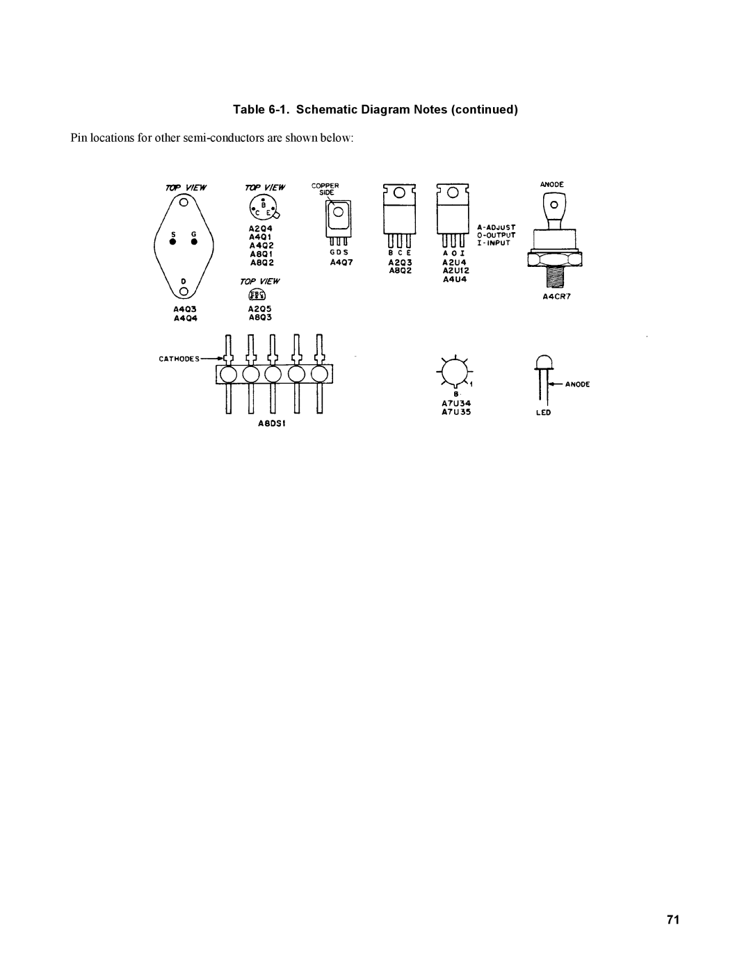
Schematic Diagram Notes (continued)
Pin locations for other
semi-conductors
are shown below:
71
Page 70
Page 72
Page 71
Image 71
Page 70
Page 72
Contents
Autoranging
Certification
Safety Summary
Printing History
Safety Symbol Definitions
Table of Contents
Replaceable Parts
Scope
Troubleshooting
Circuit Diagrams
Safety Considerations
Item Description
Manual Revisions
Operation Verification Tests
Calibration Procedure
Introduction
Test Equipment Required
Test Equipment Required
Type Required Characteristics USE Recommended Model
1KVA
Initial Setup
MON
Calibration Procedure
Iout
Vout
CR7
Performance Tests
Measurement Techniques
Constant Voltage CV Tests
Current-Monitoring Resistor Setup
Basic Test Setup
RMS Measurement Test Setup, CV Pard Test
Peak-To-Peak Measurement Test Setup, CV Pard Test
KHz Noise, CV Peak-to-Peak Pard
6023A 6028A
Load Transient Recovery Waveform
Constant Current CC Tests
CC Pard Test Setup
Initial Troubleshooting Procedures
Troubleshooting
WAVEFORM/CONDITIONS Source
Control Board Test Connector, A2J7
PIN no Signal Name
Vdc
Electrostatic Protection
Repair and Replacement
A2 Control Board Removal
A1 Main Board Removal
A4 Power Mesh Board Removal
Overall Troubleshooting Procedure
A3 Front-Panel Board Removal
Measurement
Using the Tables
Setup
Node
Main Troubleshooting Setup
Main Troubleshooting Setup
Modified Mains Cord Set For Troubleshooting
Front-Panel Troubleshooting
Troubleshooting No-Output Failures
Board
PWM-ON PWM-OFF Defective Check Functional Circuits
A2J7-26 A2J7-25
Node + Measurement Source
Troubleshooting Bias Supplies
Symptoms Defective Circuit Check Components
Symptoms Defective Check Functional Circuits Board
Node + N0DE
Node +
Measurement Source
Setup Measurement
Power Section Blocks
Troubleshooting AC-Turn-on Circuits
Setup Measurement Source
Power Limit
Troubleshooting PWM & Clock
Relay Enable
PWM-OFF
Troubleshooting DC-To-DC Converter
+ OUT
PWM-ON
Troubleshooting CC Circuit
Troubleshooting CV Circuit
A4U4OUT
Troubleshooting Down Programmer
Troubleshooting OVP Circuit
Waveforms
SET Voltage Vdc Node +
Page
Block Diagram Overview
Autoranging Power
Block Diagram
Simplified Schematic
Simplified Schematic
Down Programmer
DC-to-DC Converter
Constant-Voltage CV Circuit
Pfet Control Signals Timing Diagram
Control-Voltage Comparator
Power-Limit Comparator
Constant-Current CC Circuit
Overvoltage Protection OVP Circuit
AC-Surge Dropout Detector
Initial-Ramp Circuit
Pulse-Width Modulator PWM
Bias Voltage Detector
Display Circuits
Second-Delay Circuit
Page
Reference Designators
Replaceable Parts
Description Abbreviations
Ordering Information
CR3
Electrical Parts
CR1
CR2
Mechanical Parts
XA2P1
XA2P2
Control Board Assembly
CR3
Page
Page
Page
VR5
VR3
VR4
DS5
CR5
DS1
VR2
IC A/D Cmos 3-1/2 DGT
VR1
Pfet
NPN SI
Chassis Electrical
TS1
A4 Board Mechanical Parts
A1TB1
A2 Board Mechanical Parts
A3 Board Mechanical Parts
Option 240 240V Operation
Option 220 220V Operation
Component Location and Circuit Diagrams
Schematic Diagram Notes
Pin locations for other semi-conductors are shown below
Top View, Top Covers Removed
Main Board A1 Component Location
Control Board A2 Component Location
Front-Panel Board A3 Component Location
Power Mesh Board A4 Component Location
Page
Page
Option 002 Hardware
Specifications
General Information
Status Indicators
Table A-1. Specifications, Option Remote Programming
Input Compliance Voltage ± Current Programming Enable
Output Impedance 10.2 k ohm ± 5% Temperature Coefficient
On State logic low
Remote Trip and Remote Reset Timing
Power-on Preset
Maximum Output Voltage logic high +
Pard Typical
Table A-1. Specifications, Option Pulse Timing
Bias Supplies DC Output Ratings 25C ±
Short Circuit Output Current
Connector Assembly Procedure
Installation
Operation
Figure A-1. Mating Connector Assembly
Local/Remote Programming
Resistance Voltage or Current
Figure A-4. Calculating Value of Series Dropping Resistor
Remote Resistance Programming
Figure A-5. Remote Resistance Programming
Remote Monitoring
Remote Control
Status Indicators
Overvoltage
Remote Reset
Figure A-8. Remote Control
Power-On Preset
Multiple Supply System Shutdown
AC Dropout Buffer Circuit
Bias Supplies
Maintenance
Troubleshooting Current Programming
Troubleshooting Resistance and Voltage Programming
Figure A-11. Troubleshooting Current Programming of CV Mode
Figure A-13. Troubleshooting Status Indicators
Page
REF. Desig Model no Description
Table A-3. Replacement Parts
100
101
VR9
Definitions
Indicator and Qualifier Symbols
OLD Symbol NEW Symbol
Logic Symbols and Definitions 102
Schematic Diagram Notes 103
Schematic Notes
Figure A-15. Option 002 Board, Component Location 104
Schematic Notes
Figure A-16. Option 002 Board, Schematic Diagram 105
Page
107
Model 6023A
Model 6028A
108
From
Top
Page
Image
Contents