cycle power | five 100ms pulses then hi | |||
cycle power | two 200ms pulses then hi | |||
cycle power | transition lo to hi at 800 msec | |||
cycle power | transition lo to hi at 1.0 sec | |||
cycle power | transition lo to hi at 1.1 sec | |||
|
| A2Q5 (col) | cycle power | transistion 5.0 to 0.3Vdc at 1.0s |
| DROPOUT | |||
(RELAY ENABLE) |
|
| ||
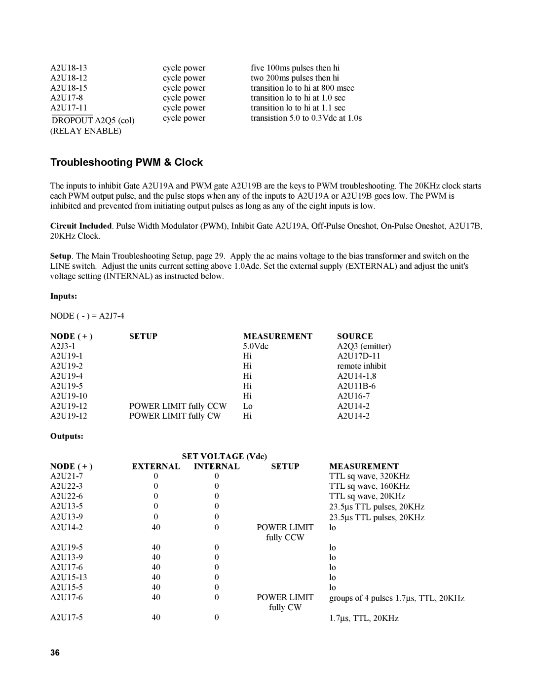
Troubleshooting PWM & Clock
The inputs to inhibit Gate A2U19A and PWM gate A2U19B are the keys to PWM troubleshooting. The 20KHz clock starts each PWM output pulse, and the pulse stops when any of the inputs to A2U19A or A2U19B goes low. The PWM is inhibited and prevented from initiating output pulses as long as any of the eight inputs is low.
Circuit Included. Pulse Width Modulator (PWM), Inhibit Gate A2U19A,
Setup. The Main Troubleshooting Setup, page 29. Apply the ac mains voltage to the bias transformer and switch on the LINE switch. Adjust the units current setting above 1.0Adc. Set the external supply (EXTERNAL) and adjust the unit's voltage setting (INTERNAL) as instructed below.
Inputs:
NODE ( - ) =
NODE ( + ) | SETUP | MEASUREMENT | SOURCE |
| 5.0Vdc | A2Q3 (emitter) | |
| Hi | ||
| Hi | remote inhibit | |
| Hi | ||
| Hi | ||
| Hi | ||
POWER LIMIT fully CCW | Lo | ||
POWER LIMIT fully CW | Hi |
Outputs: |
|
|
|
|
|
| SET VOLTAGE (Vdc) |
| |
NODE ( + ) | EXTERNAL | INTERNAL | SETUP | MEASUREMENT |
0 | 0 |
| TTL sq wave, 320KHz | |
0 | 0 |
| TTL sq wave, 160KHz | |
0 | 0 |
| TTL sq wave, 20KHz | |
0 | 0 |
| 23.5∝s TTL pulses, 20KHz | |
0 | 0 |
| 23.5∝s TTL pulses, 20KHz | |
40 | 0 | POWER LIMIT | lo | |
40 | 0 | fully CCW | lo | |
| ||||
40 | 0 |
| lo | |
40 | 0 |
| lo | |
40 | 0 |
| lo | |
40 | 0 |
| lo | |
40 | 0 | POWER LIMIT | groups of 4 pulses 1.7∝s, TTL, 20KHz | |
40 | 0 | fully CW | 1.7∝s, TTL, 20KHz | |
| ||||
36