+ OUT | 40 | 10 | 3.8Vdc (OVERRANGE) |
+ OUT | 40 | 2 | 2.0Vdc (CV) |
+ OUT | 40 | 2 | short |
|
|
|
Troubleshooting DC-To-DC Converter
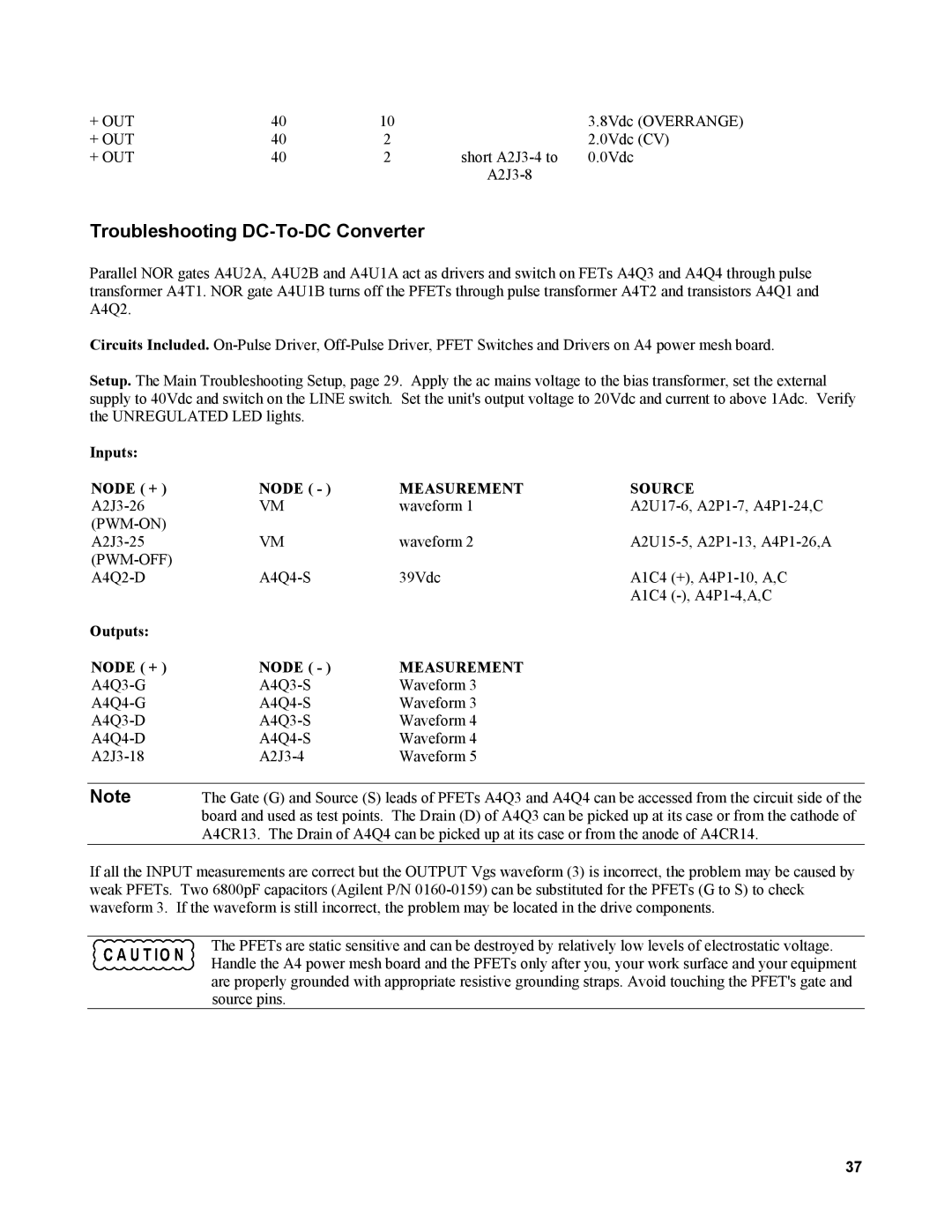
Parallel NOR gates A4U2A, A4U2B and A4U1A act as drivers and switch on FETs A4Q3 and A4Q4 through pulse transformer A4T1. NOR gate A4U1B turns off the PFETs through pulse transformer A4T2 and transistors A4Q1 and A4Q2.
Circuits Included.
Setup. The Main Troubleshooting Setup, page 29. Apply the ac mains voltage to the bias transformer, set the external supply to 40Vdc and switch on the LINE switch. Set the unit's output voltage to 20Vdc and current to above 1Adc. Verify the UNREGULATED LED lights.
Inputs: |
|
|
|
NODE ( + ) | NODE ( - ) | MEASUREMENT | SOURCE |
VM | waveform 1 | ||
|
|
|
|
VM | waveform 2 | ||
|
|
|
|
39Vdc | A1C4 (+), | ||
|
|
| A1C4 |
Outputs: |
|
|
|
NODE ( + ) | NODE ( - ) | MEASUREMENT |
|
Waveform 3 |
| ||
Waveform 3 |
| ||
Waveform 4 |
| ||
Waveform 4 |
| ||
Waveform 5 |
|
Note | The Gate (G) and Source (S) leads of PFETs A4Q3 and A4Q4 can be accessed from the circuit side of the |
| board and used as test points. The Drain (D) of A4Q3 can be picked up at its case or from the cathode of |
| A4CR13. The Drain of A4Q4 can be picked up at its case or from the anode of A4CR14. |
If all the INPUT measurements are correct but the OUTPUT Vgs waveform (3) is incorrect, the problem may be caused by weak PFETs. Two 6800pF capacitors (Agilent P/N
The PFETs are static sensitive and can be destroyed by relatively low levels of electrostatic voltage. Handle the A4 power mesh board and the PFETs only after you, your work surface and your equipment are properly grounded with appropriate resistive grounding straps. Avoid touching the PFET's gate and source pins.
37
