Table
Printed Circuit | Block Name | Circuit Within | Ref. |
| Perform These | ||
| Board |
|
| Block | Designator |
| Procedures* |
A1 Main Board |
|
|
| R3 |
| 4 | |
A1 | Main Board |
|
|
| T1 |
| 4 then 5 |
A4 | Power Mesh |
|
|
| T3 |
| 4 then 5 Board |
A4 Power Mesh |
|
|
| CR7 |
| 4 then 5 Board | |
A2 | Control Board | Constant Voltage | All Except Current | All |
| 1 then 2 | |
|
| (CV) Circuit |
| Source |
|
|
|
A2 | Control Board | Constant Voltage | Current Source | All |
| 6 | |
|
| (CV) Circuit |
|
|
|
|
|
A2 | Control Board | Constant Current |
|
| All |
| 3 then 4 |
|
| (CC) Circuit |
|
|
|
|
|
A2 | Control Board | Power Limit |
|
| All |
| 4 then 5 |
|
| Comparator |
|
|
|
|
|
A2 | Control Board | Bias Power Supplies | ± 15V Supplies | All |
| All | |
A2 | Control Board |
|
|
| U9, R79, R80, R24 |
| 7 |
|
| * Code To Calibration Procedure To Be Performed |
| ||||
1. | 4. |
| |||||
2. | 5. | Power Limit Calibration |
| ||||
3. | 6. Resistance Programming Full Scale (F/S) Calibration | ||||||
|
|
| 7. | Meter Full Scale (F/S) Calibration |
| ||
Performance Tests
The following paragraphs provide test procedures for verifying the unit's compliance with the specifications of Table
Measurement Techniques
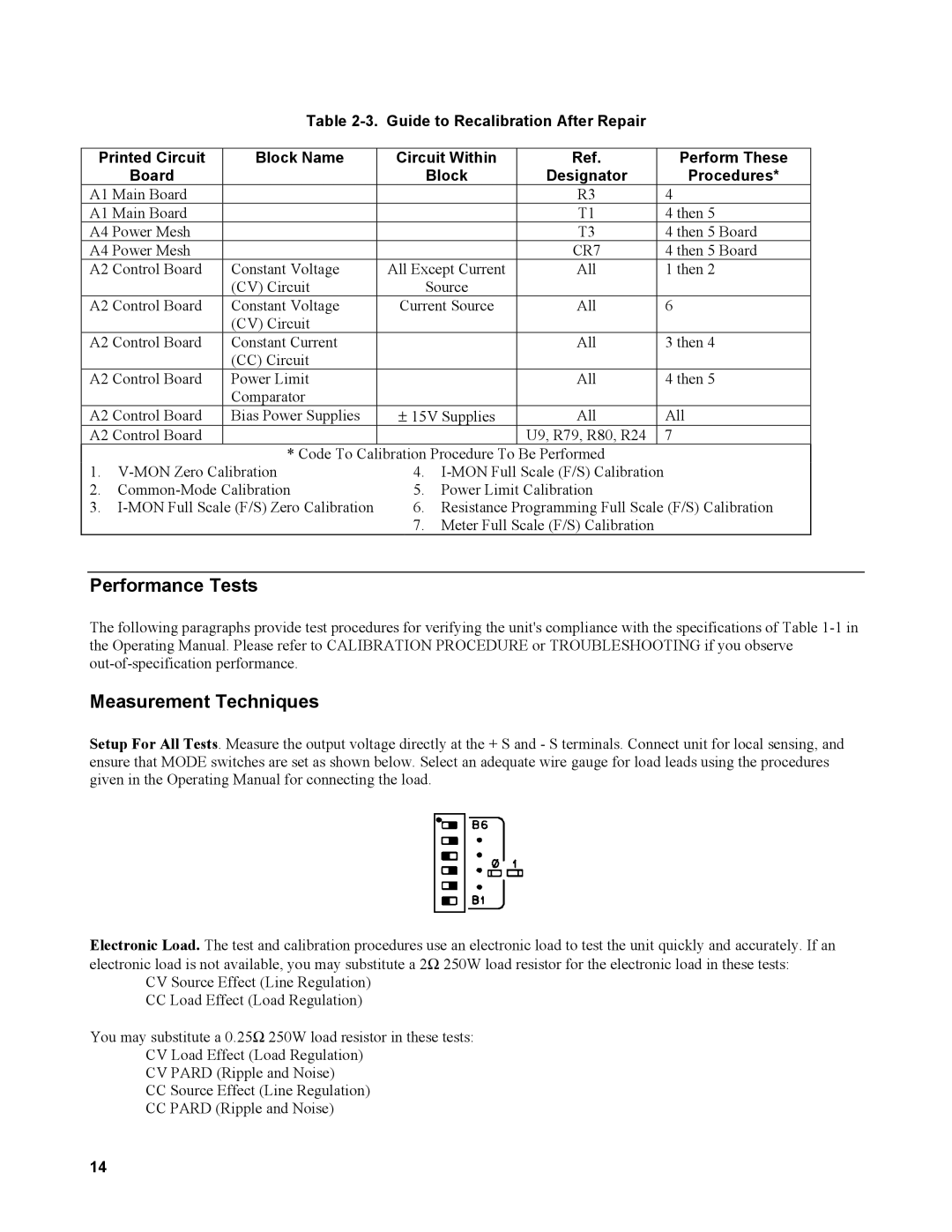
Setup For All Tests. Measure the output voltage directly at the + S and - S terminals. Connect unit for local sensing, and ensure that MODE switches are set as shown below. Select an adequate wire gauge for load leads using the procedures given in the Operating Manual for connecting the load.
Electronic Load. The test and calibration procedures use an electronic load to test the unit quickly and accurately. If an electronic load is not available, you may substitute a 2Ω 250W load resistor for the electronic load in these tests:
CV Source Effect (Line Regulation)
CC Load Effect (Load Regulation)
You may substitute a 0.25Ω 250W load resistor in these tests:
CV Load Effect (Load Regulation)
CV PARD (Ripple and Noise)
CCSource Effect (Line Regulation) CC PARD (Ripple and Noise)
14