Table
(Bias supplies and AC
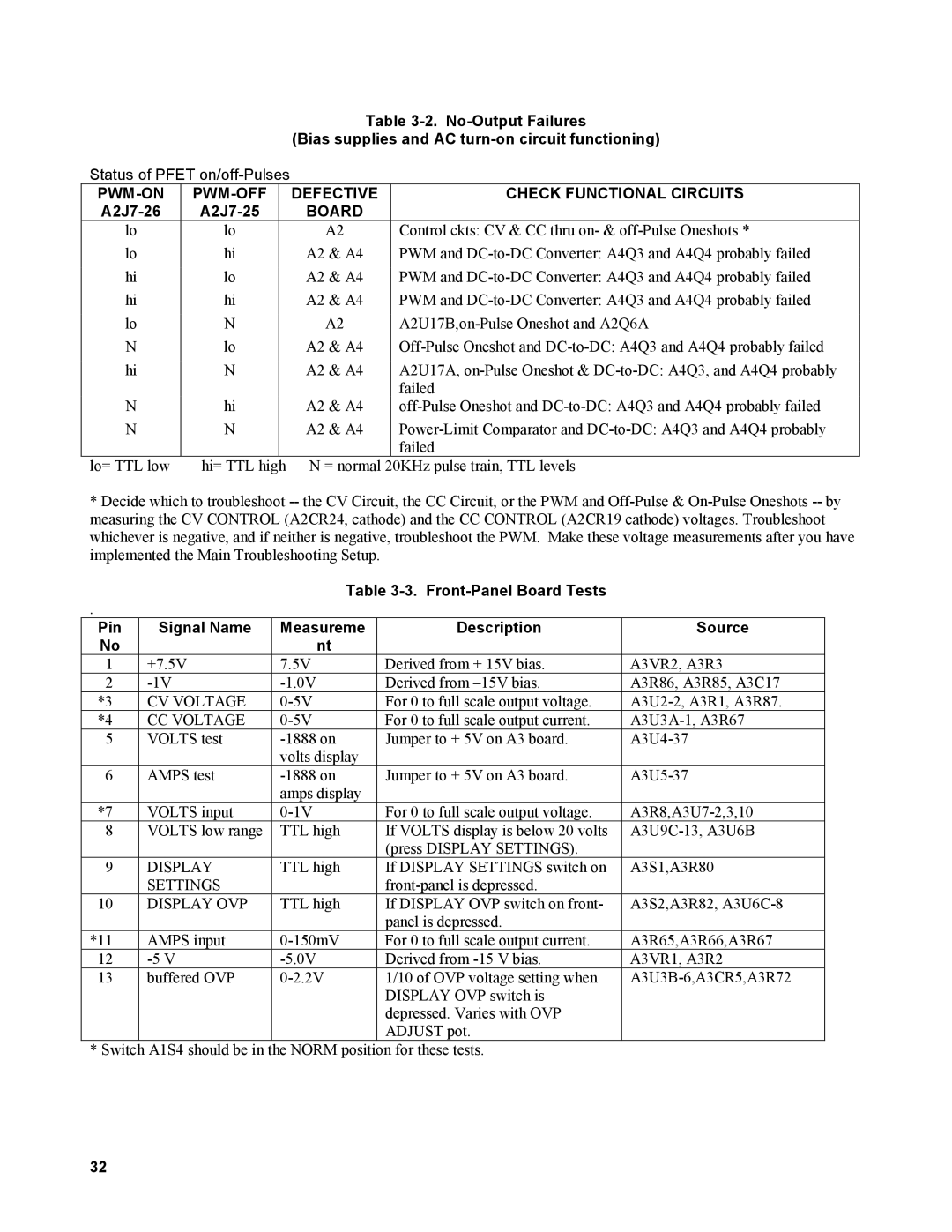
Status of PFET
|
| DEFECTIVE | CHECK FUNCTIONAL CIRCUITS |
|
| BOARD |
|
lo | lo | A2 | Control ckts: CV & CC thru on- & |
lo | hi | A2 & A4 | PWM and |
hi | lo | A2 & A4 | PWM and |
hi | hi | A2 & A4 | PWM and |
lo | N | A2 | |
N | lo | A2 & A4 | |
hi | N | A2 & A4 | A2U17A, |
|
|
| failed |
N | hi | A2 & A4 | |
N | N | A2 & A4 | |
|
|
| failed |
lo= TTL low | hi= TTL high | N = normal 20KHz pulse train, TTL levels | |
*Decide which to troubleshoot
Table
.
Pin | Signal Name | Measureme | Description | Source |
No |
| nt |
|
|
1 | +7.5V | 7.5V | Derived from + 15V bias. | A3VR2, A3R3 |
2 | Derived from | A3R86, A3R85, A3C17 | ||
*3 | CV VOLTAGE | For 0 to full scale output voltage. | ||
*4 | CC VOLTAGE | For 0 to full scale output current. | ||
5 | VOLTS test | Jumper to + 5V on A3 board. | ||
|
| volts display |
|
|
6 | AMPS test | Jumper to + 5V on A3 board. | ||
|
| amps display |
|
|
*7 | VOLTS input | For 0 to full scale output voltage. | ||
8 | VOLTS low range | TTL high | If VOLTS display is below 20 volts | |
|
|
| (press DISPLAY SETTINGS). |
|
9 | DISPLAY | TTL high | If DISPLAY SETTINGS switch on | A3S1,A3R80 |
| SETTINGS |
|
| |
10 | DISPLAY OVP | TTL high | If DISPLAY OVP switch on front- | A3S2,A3R82, |
|
|
| panel is depressed. |
|
*11 | AMPS input | For 0 to full scale output current. | A3R65,A3R66,A3R67 | |
12 | Derived from | A3VR1, A3R2 | ||
13 | buffered OVP | 1/10 of OVP voltage setting when | ||
|
|
| DISPLAY OVP switch is |
|
|
|
| depressed. Varies with OVP |
|
|
|
| ADJUST pot. |
|
* Switch A1S4 should be in the NORM position for these tests.
32