| Table |
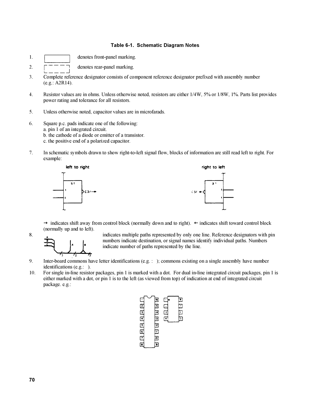
1. | denotes |
2. | denotes |
3.Complete reference designator consists of component reference designator prefixed with assembly number (e.g.: A2R14).
4.Resistor values are in ohms. Unless otherwise noted, resistors are either 1/4W, 5% or 1/8W, 1%. Parts list provides power rating and tolerance for all resistors.
5.Unless otherwise noted, capacitor values are in microfarads.
6.Square p.c. pads indicate one of the following:
a.pin 1 of an integrated circuit.
b.the cathode of a diode or emitter of a transistor.
c.the positive end of a polarized capacitor.
7.In schematic symbols drawn to show
žindicates shift away from control block (normally down and to right). • indicates shift toward control block (normally up and to left).
8. | indicates multiple paths represented by only one line. Reference designators with pin |
| numbers indicate destination, or signal names identify individual paths. Numbers |
| indicate number of paths represented by the line. |
9.
identifications (e.g.: ).
10.For single
70
