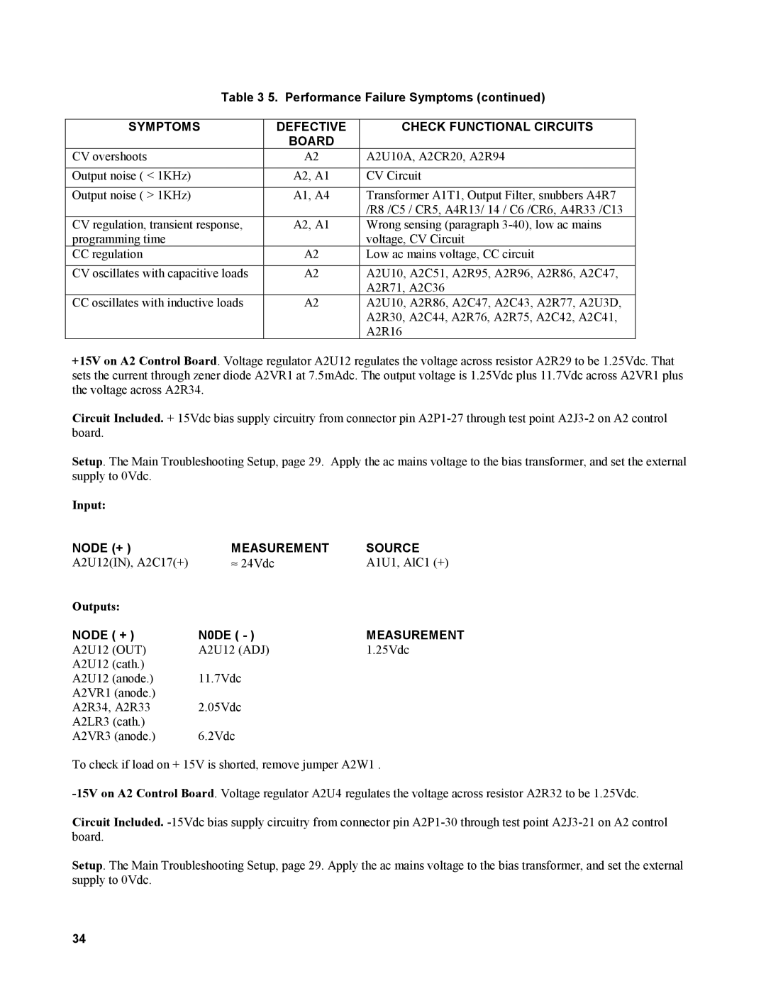
Table 3 5. Performance Failure Symptoms (continued)
SYMPTOMS | DEFECTIVE | CHECK FUNCTIONAL CIRCUITS |
| BOARD |
|
CV overshoots | A2 | A2U10A, A2CR20, A2R94 |
|
|
|
Output noise ( < 1KHz) | A2, A1 | CV Circuit |
|
|
|
Output noise ( > 1KHz) | A1, A4 | Transformer A1T1, Output Filter, snubbers A4R7 |
|
| /R8 /C5 / CR5, A4R13/ 14 / C6 /CR6, A4R33 /C13 |
CV regulation, transient response, | A2, A1 | Wrong sensing (paragraph |
programming time |
| voltage, CV Circuit |
CC regulation | A2 | Low ac mains voltage, CC circuit |
|
|
|
CV oscillates with capacitive loads | A2 | A2U10, A2C51, A2R95, A2R96, A2R86, A2C47, |
|
| A2R71, A2C36 |
CC oscillates with inductive loads | A2 | A2U10, A2R86, A2C47, A2C43, A2R77, A2U3D, |
|
| A2R30, A2C44, A2R76, A2R75, A2C42, A2C41, |
|
| A2R16 |
+15V on A2 Control Board. Voltage regulator A2U12 regulates the voltage across resistor A2R29 to be 1.25Vdc. That sets the current through zener diode A2VR1 at 7.5mAdc. The output voltage is 1.25Vdc plus 11.7Vdc across A2VR1 plus the voltage across A2R34.
Circuit Included. + 15Vdc bias supply circuitry from connector pin
Setup. The Main Troubleshooting Setup, page 29. Apply the ac mains voltage to the bias transformer, and set the external supply to 0Vdc.
Input:
NODE (+ ) | MEASUREMENT | SOURCE |
A2U12(IN), A2C17(+) | ≈ 24Vdc | A1U1, AlC1 (+) |
Outputs: |
|
|
NODE ( + ) | N0DE ( - ) | MEASUREMENT |
A2U12 (OUT) | A2U12 (ADJ) | 1.25Vdc |
A2U12 (cath.) |
|
|
A2U12 (anode.) | 11.7Vdc |
|
A2VR1 (anode.) |
|
|
A2R34, A2R33 | 2.05Vdc |
|
A2LR3 (cath.) |
|
|
A2VR3 (anode.) | 6.2Vdc |
|
To check if load on + 15V is shorted, remove jumper A2W1 .
Circuit Included.
Setup. The Main Troubleshooting Setup, page 29. Apply the ac mains voltage to the bias transformer, and set the external supply to 0Vdc.
34
