Table 2-2. Calibration Procedure (continued)
TEST | TESTED | TEST POINTS |
| TEST SEQUENCE AND ADJUSTMENTS | EXPECTED | |||
| VARIABLE |
|
|
|
|
| RESULTS | |
Power | V(OUT) |
| a. |
| Perform | 30.2A 7.55V for | ||
Limit | I(OUT) |
|
|
| proceeding. | CC operation | ||
Adjust. |
|
|
| b. |
| Connect the unit to the ac power line via the | (6023A) | |
|
|
|
|
|
| external variable | 10.2A, 23V for | |
|
|
|
|
|
| to nominal line voltage. | ||
|
|
|
| c. | Connect a 0.25Ω, 250W (6023A), 2.3Ω, | CC operation | ||
|
|
|
|
|
| 250W (6028A) resistor across the unit's output | (6028A) | |
|
|
|
|
|
| and turn on ac power. |
| |
|
|
|
| d. | Set voltage control to 9V (6023A) 9V≥ 3V |
| ||
|
|
|
|
|
| (6028A) and current control to 30.2A |
| |
|
|
|
|
|
| (6023A), 10.2A (6028A) |
| |
|
|
|
| e. |
| Set |
| |
|
|
|
|
|
| voltage. |
| |
|
|
|
| f. |
| Turn A2R25 fully counterclockwise. |
| |
|
|
|
| g. | Slowly adjust A2R25 clockwise until CC |
| ||
|
|
|
|
|
| LED just lights. |
| |
|
|
|
|
|
|
|
|
|
|
|
|
|
|
|
|
|
|
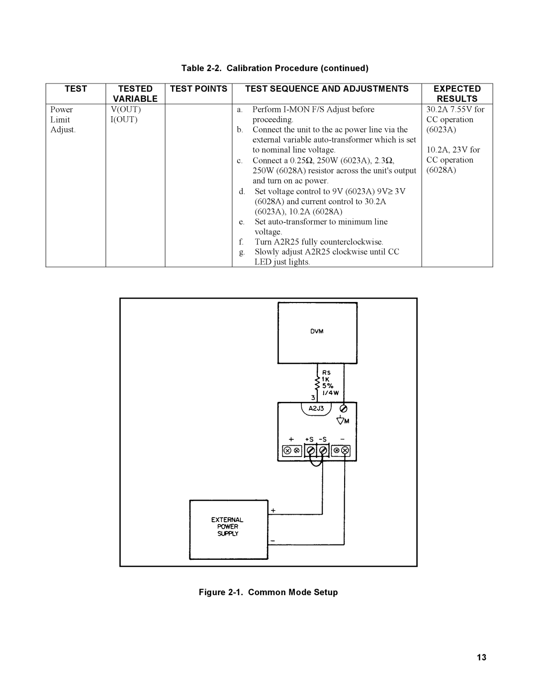
Figure 2-1. Common Mode Setup
13