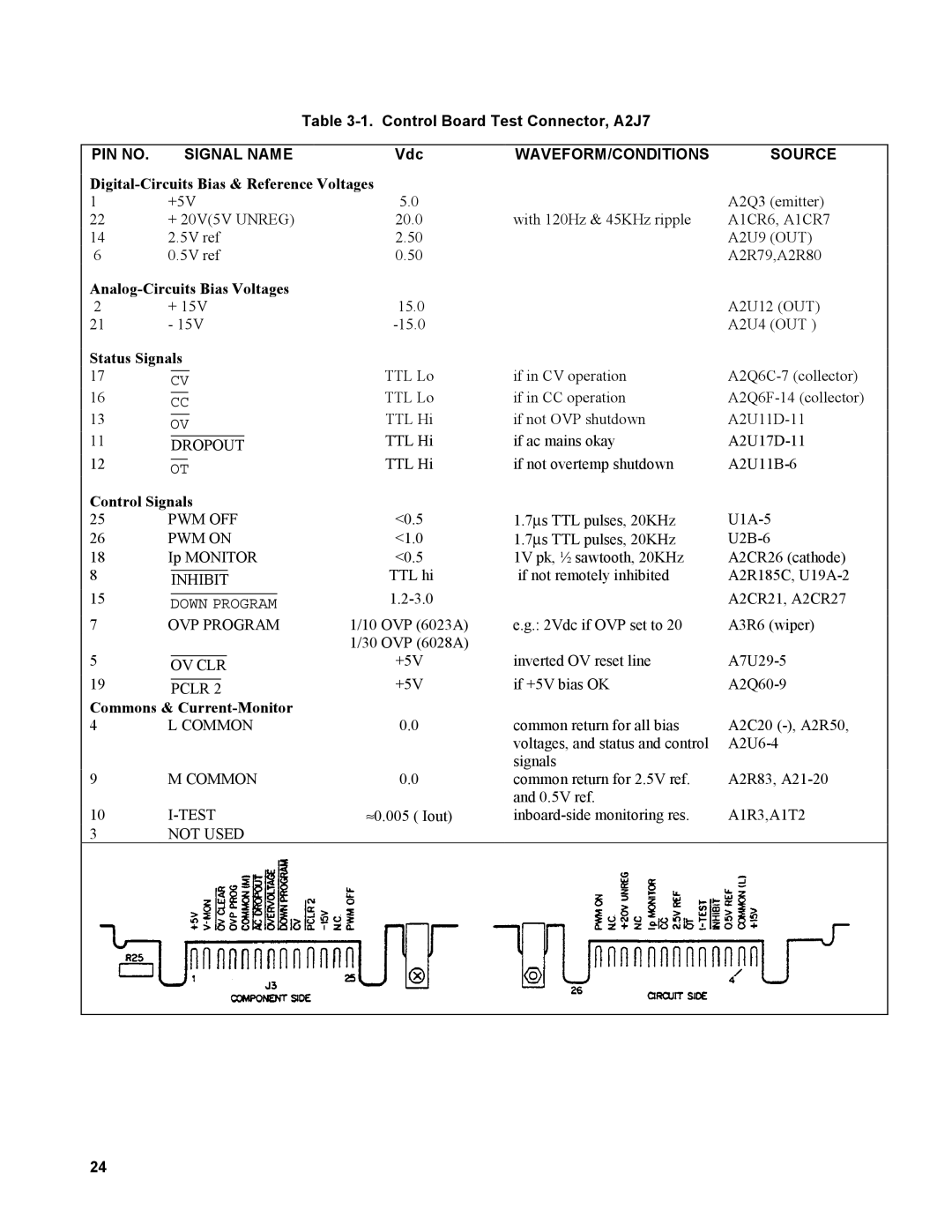
Table 3-1. Control Board Test Connector, A2J7
PIN NO. |
|
| SIGNAL NAME | Vdc | WAVEFORM/CONDITIONS | SOURCE | |||||||
|
|
| |||||||||||
|
| ||||||||||||
1 | +5V | 5.0 |
| A2Q3 (emitter) | |||||||||
22 | + 20V(5V UNREG) | 20.0 | with 120Hz & 45KHz ripple | A1CR6, A1CR7 | |||||||||
14 | 2.5V ref | 2.50 |
| A2U9 (OUT) | |||||||||
6 | 0.5V ref | 0.50 |
| A2R79,A2R80 | |||||||||
|
|
| |||||||||||
2 | + 15V | 15.0 |
| A2U12 (OUT) | |||||||||
21 | - 15V |
| A2U4 (OUT ) | ||||||||||
Status Signals |
|
|
| ||||||||||
17 |
|
|
|
|
|
|
|
|
|
| TTL Lo | if in CV operation | |
| CV | ||||||||||||
16 |
|
|
|
|
|
|
|
|
| TTL Lo | if in CC operation | ||
| CC | ||||||||||||
13 |
|
|
|
|
|
|
|
|
| TTL Hi | if not OVP shutdown | ||
| OV | ||||||||||||
11 |
|
|
|
|
|
|
|
|
|
| TTL Hi | if ac mains okay | |
| DROPOUT | ||||||||||||
12 |
|
|
|
|
|
|
| TTL Hi | if not overtemp shutdown | ||||
| OT | ||||||||||||
Control Signals |
|
|
| ||||||||||
25 | PWM OFF | <0.5 | 1.7∝s TTL pulses, 20KHz | ||||||||||
26 | PWM ON | <1.0 | 1.7∝s TTL pulses, 20KHz | ||||||||||
18 | Ip MONITOR | <0.5 | 1V pk, ½ sawtooth, 20KHz | A2CR26 (cathode) | |||||||||
8 |
|
|
|
|
|
| TTL hi | if not remotely inhibited | A2R185C, | ||||
| INHIBIT | ||||||||||||
15 |
|
|
|
|
|
| A2CR21, A2CR27 | ||||||
| DOWN PROGRAM |
| |||||||||||
7 | OVP PROGRAM | 1/10 OVP (6023A) | e.g.: 2Vdc if OVP set to 20 | A3R6 (wiper) | |||||||||
5 |
|
|
|
|
|
|
|
|
|
| 1/30 OVP (6028A) |
|
|
|
|
|
|
| +5V | inverted OV reset line | |||||||
| OV CLR | ||||||||||||
19 |
|
|
| +5V | if +5V bias OK | ||||||||
| PCLR 2 | ||||||||||||
Commons & |
|
|
| ||||||||||
4 | L COMMON | 0.0 | common return for all bias | A2C20 | |||||||||
|
|
|
|
|
|
|
|
|
|
|
| voltages, and status and control | |
|
|
|
|
|
|
|
|
|
|
|
| signals |
|
9 | M COMMON | 0.0 | common return for 2.5V ref. | A2R83, | |||||||||
|
|
|
|
|
|
|
|
|
|
|
| and 0.5V ref. |
|
10 | ≈0.005 ( Iout) | A1R3,A1T2 | |||||||||||
3 | NOT USED |
|
|
| |||||||||
|
|
|
|
|
|
|
|
|
|
|
|
|
|
24