|
| Table |
|
|
|
|
|
|
|
CODE | TITLE | DESCRIPTION |
|
|
# |
|
| ||
|
|
|
| |
|
| MODEL |
|
|
|
|
|
|
|
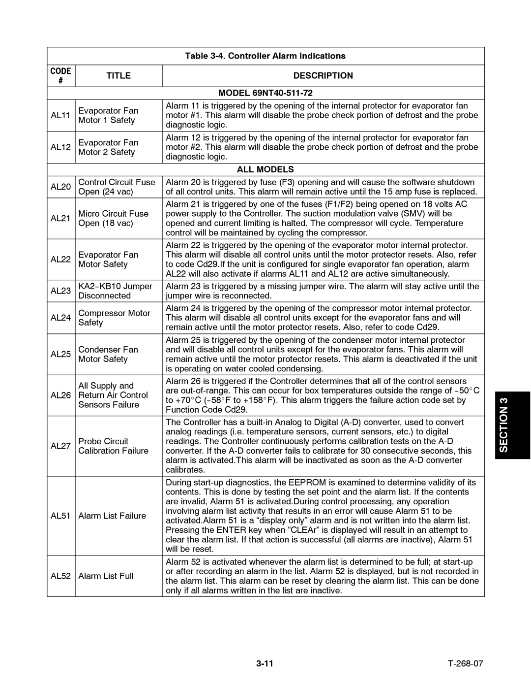
| Evaporator Fan | Alarm 11 is triggered by the opening of the internal protector for evaporator fan |
|
|
AL11 | motor #1. This alarm will disable the probe check portion of defrost and the probe |
|
| |
| Motor 1 Safety | diagnostic logic. |
|
|
|
|
|
| |
|
|
|
|
|
| Evaporator Fan | Alarm 12 is triggered by the opening of the internal protector for evaporator fan |
|
|
AL12 | motor #2. This alarm will disable the probe check portion of defrost and the probe |
|
| |
| Motor 2 Safety | diagnostic logic. |
|
|
|
|
|
| |
|
|
|
|
|
|
| ALL MODELS |
|
|
|
|
|
|
|
AL20 | Control Circuit Fuse | Alarm 20 is triggered by fuse (F3) opening and will cause the software shutdown |
|
|
| Open (24 vac) | of all control units. This alarm will remain active until the 15 amp fuse is replaced. |
|
|
|
| Alarm 21 is triggered by one of the fuses (F1/F2) being opened on 18 volts AC |
|
|
AL21 | Micro Circuit Fuse | power supply to the Controller. The suction modulation valve (SMV) will be |
|
|
| Open (18 vac) | opened and current limiting is halted. The compressor will cycle. Temperature |
|
|
|
| control will be maintained by cycling the compressor. |
|
|
|
| Alarm 22 is triggered by the opening of the evaporator motor internal protector. |
|
|
AL22 | Evaporator Fan | This alarm will disable all control units until the motor protector resets. Also, refer |
|
|
| Motor Safety | to code Cd29.If the unit is configured for single evaporator fan operation, alarm |
|
|
|
| AL22 will also activate if alarms AL11 and AL12 are active simultaneously. |
|
|
AL23 | Alarm 23 is triggered by a missing jumper wire. The alarm will stay active until the |
|
| |
| Disconnected | jumper wire is reconnected. |
|
|
| Compressor Motor | Alarm 24 is triggered by the opening of the compressor motor internal protector. |
|
|
AL24 | This alarm will disable all control units except for the evaporator fans and will |
|
| |
| Safety | remain active until the motor protector resets. Also, refer to code Cd29. |
|
|
|
|
|
| |
|
|
|
|
|
|
| Alarm 25 is triggered by the opening of the condenser motor internal protector |
|
|
AL25 | Condenser Fan | and will disable all control units except for the evaporator fans. This alarm will |
|
|
| Motor Safety | remain active until the motor protector resets. This alarm is deactivated if the unit |
|
|
|
| is operating on water cooled condensing. |
|
|
| All Supply and | Alarm 26 is triggered if the Controller determines that all of the control sensors |
|
|
| are |
|
| |
AL26 | Return Air Control |
|
| |
| ||||
to +70_C |
| 3 | ||
| Sensors Failure |
| ||
| Function Code Cd29. |
| SECTION | |
|
|
| ||
|
|
|
| |
|
| The Controller has a |
| |
|
|
|
| |
|
| analog readings (i.e. temperature sensors, current sensors, etc.) to digital |
|
|
AL27 | Probe Circuit | readings. The Controller continuously performs calibration tests on the |
|
|
| Calibration Failure | converter. If the |
|
|
|
| alarm is activated.This alarm will be inactivated as soon as the |
|
|
|
|
| ||
|
| calibrates. |
|
|
|
|
|
|
|
|
| During |
|
|
|
| contents. This is done by testing the set point and the alarm list. If the contents |
|
|
|
| are invalid, Alarm 51 is activated.During control processing, any operation |
|
|
AL51 | Alarm List Failure | involving alarm list activity that results in an error will cause Alarm 51 to be |
|
|
activated.Alarm 51 is a “display only” alarm and is not written into the alarm list. |
|
| ||
|
|
|
| |
|
| Pressing the ENTER key when “CLEAr” is displayed will result in an attempt to |
|
|
|
| clear the alarm list. If that action is successful (all alarms are inactive), Alarm 51 |
|
|
|
| will be reset. |
|
|
|
| Alarm 52 is activated whenever the alarm list is determined to be full; at |
|
|
AL52 | Alarm List Full | or after recording an alarm in the list. Alarm 52 is displayed, but is not recorded in |
|
|
the alarm list. This alarm can be reset by clearing the alarm list. This can be done |
|
| ||
|
|
|
| |
|
| only if all alarms written in the list are inactive. |
|
|
Page 49
Image 49