CODE | TITLE |
| DESCRIPTION |
|
|
# |
|
|
| ||
|
|
|
|
| |
|
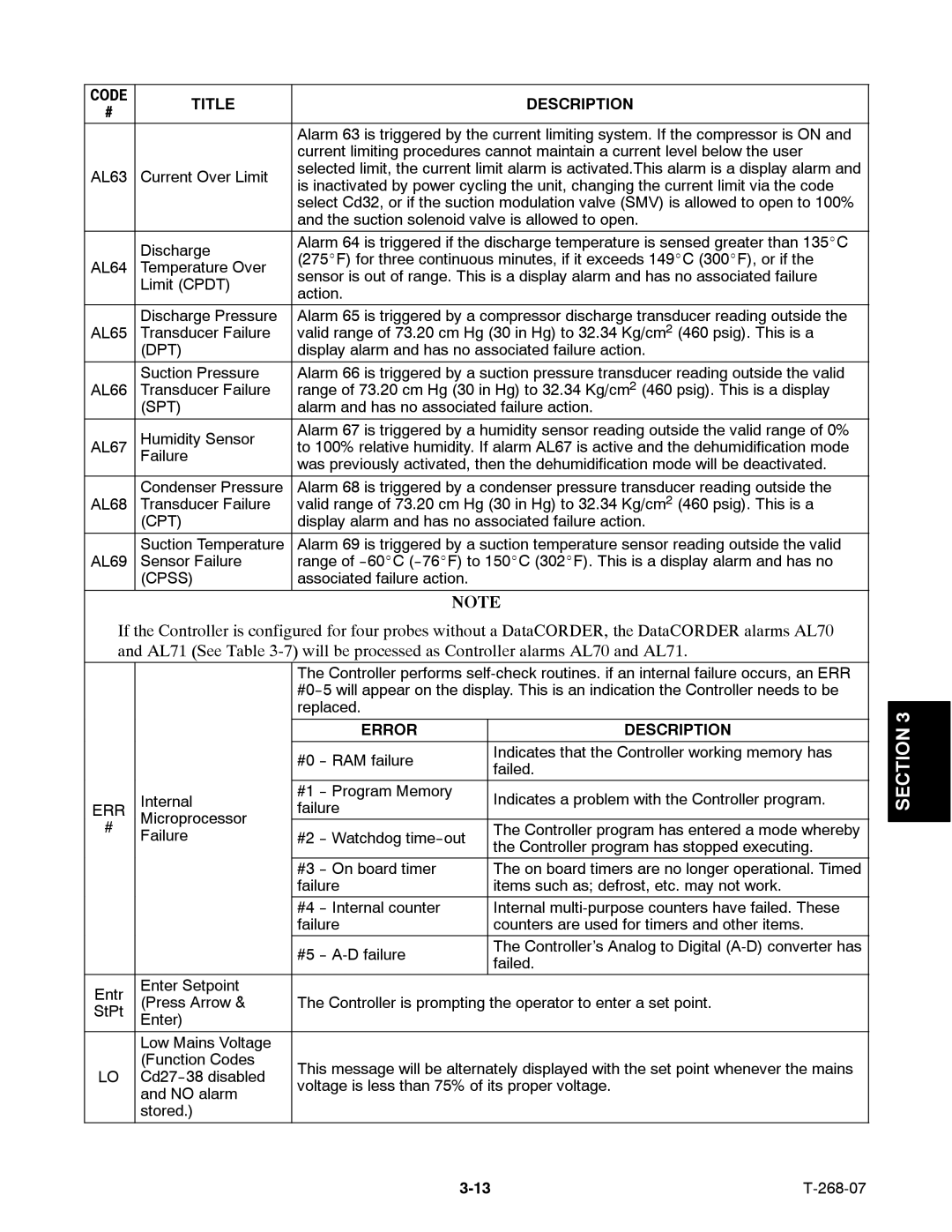
| Alarm 63 is triggered by the current limiting system. If the compressor is ON and |
|
| |
|
| current limiting procedures cannot maintain a current level below the user |
|
| |
AL63 | Current Over Limit | selected limit, the current limit alarm is activated.This alarm is a display alarm and |
|
| |
is inactivated by power cycling the unit, changing the current limit via the code |
|
| |||
|
|
|
| ||
|
| select Cd32, or if the suction modulation valve (SMV) is allowed to open to 100% |
|
| |
|
| and the suction solenoid valve is allowed to open. |
|
| |
| Discharge | Alarm 64 is triggered if the discharge temperature is sensed greater than 135_C |
|
| |
| (275_F) for three continuous minutes, if it exceeds 149_C (300_F), or if the |
|
| ||
AL64 | Temperature Over |
|
| ||
sensor is out of range. This is a display alarm and has no associated failure |
|
| |||
| Limit (CPDT) |
|
| ||
| action. |
|
|
| |
|
|
|
|
| |
|
|
|
|
|
|
| Discharge Pressure | Alarm 65 is triggered by a compressor discharge transducer reading outside the |
|
| |
AL65 | Transducer Failure | valid range of 73.20 cm Hg (30 in Hg) to 32.34 Kg/cm2 (460 psig). This is a |
|
| |
| (DPT) | display alarm and has no associated failure action. |
|
| |
|
|
|
|
|
|
| Suction Pressure | Alarm 66 is triggered by a suction pressure transducer reading outside the valid |
|
| |
AL66 | Transducer Failure | range of 73.20 cm Hg (30 in Hg) to 32.34 Kg/cm2 (460 psig). This is a display |
|
| |
| (SPT) | alarm and has no associated failure action. |
|
| |
|
|
|
|
|
|
| Humidity Sensor | Alarm 67 is triggered by a humidity sensor reading outside the valid range of 0% |
|
| |
AL67 | to 100% relative humidity. If alarm AL67 is active and the dehumidification mode |
|
| ||
| Failure | was previously activated, then the dehumidification mode will be deactivated. |
|
| |
|
|
|
| ||
|
|
|
|
|
|
| Condenser Pressure | Alarm 68 is triggered by a condenser pressure transducer reading outside the |
|
| |
AL68 | Transducer Failure | valid range of 73.20 cm Hg (30 in Hg) to 32.34 Kg/cm2 (460 psig). This is a |
|
| |
| (CPT) | display alarm and has no associated failure action. |
|
| |
|
|
|
|
|
|
| Suction Temperature | Alarm 69 is triggered by a suction temperature sensor reading outside the valid |
|
| |
AL69 | Sensor Failure | range of |
|
| |
| (CPSS) | associated failure action. |
|
|
|
|
|
|
|
|
|
|
| NOTE |
|
| |
If the Controller is configured for four probes without a DataCORDER, the DataCORDER alarms AL70 |
|
| |||
and AL71 (See Table |
|
| |||
|
| The Controller performs |
|
| |
|
|
|
| ||
|
| replaced. |
|
|
|
|
|
|
| 3 | |
|
|
|
|
| |
|
| ERROR | DESCRIPTION |
| SECTION |
|
|
|
|
| |
|
| #0 | Indicates that the Controller working memory has |
| |
|
| failed. |
| ||
|
|
|
| ||
| Internal | #1 | Indicates a problem with the Controller program. |
| |
ERR | failure |
| |||
Microprocessor |
|
|
| ||
# |
| The Controller program has entered a mode whereby |
|
| |
Failure | #2 |
|
| ||
| the Controller program has stopped executing. |
|
| ||
|
|
|
|
| |
|
|
|
|
|
|
|
| #3 | The on board timers are no longer operational. Timed |
|
|
|
| failure | items such as; defrost, etc. may not work. |
|
|
|
| #4 | Internal |
|
|
|
| failure | counters are used for timers and other items. |
|
|
|
| #5 | The Controller’s Analog to Digital |
|
|
|
| failed. |
|
| |
|
|
|
|
| |
Entr | Enter Setpoint |
|
|
|
|
(Press Arrow & | The Controller is prompting the operator to enter a set point. |
|
| ||
StPt | Enter) |
|
|
|
|
|
|
|
|
|
|
| Low Mains Voltage |
|
|
|
|
| (Function Codes | This message will be alternately displayed with the set point whenever the mains |
|
| |
LO |
|
| |||
voltage is less than 75% of its proper voltage. |
|
| |||
| and NO alarm |
|
| ||
|
|
|
|
| |
| stored.) |
|
|
|
|
|
|
|
|
|
|
Page 51
Image 51