Manuals
/
Carrier
/
Kitchen Appliance
/
Refrigerator
Carrier
69NT40-521, 69NT40-511-199
manual
Heating Mode 268-07
Models:
69NT40-521
69NT40-511-1
69NT40-511-199
1
86
138
138
Download
138 pages
33.05 Kb
83
84
85
86
87
88
89
90
Troubleshooting
Install
Model Chart
Controller Alarms
Error Description
Maintenance
Configuration Software
PRE-TRIP Diagnostics
Access to DataCORDER Functions
Compressor Disassembly
Page 86
Image 86
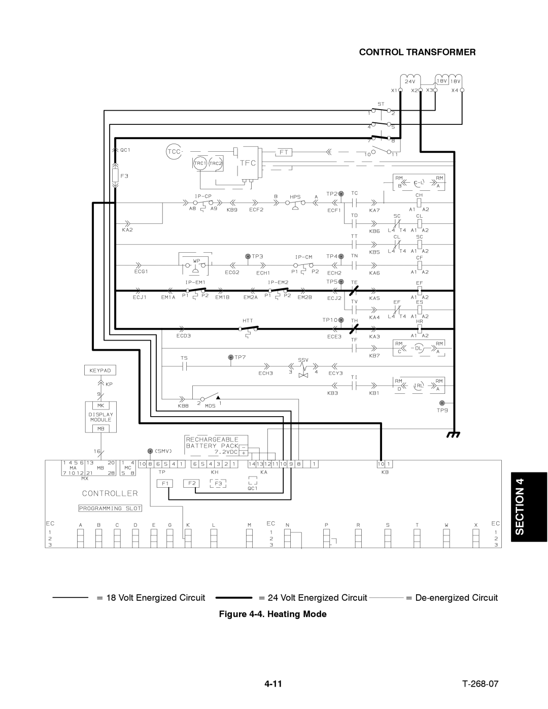
CONTROL TRANSFORMER
SECTION 4
= 18 Volt Energized Circuit
= 24 Volt Energized Circuit
=
De-energized
Circuit
Figure
4-4.
Heating Mode
4-11
T-268-07
Page 85
Page 87
Page 86
Image 86
Page 85
Page 87
Contents
Container Refrigeration Unit
Operation Container Refrigeration Unit Models
Maintenance Precautions
General Safety Notices
Operating Precautions
Safety-1 268-07
Safety-2
Specific Warning and Caution Statements
Table of Contents
Operation
Section Service
Iii 268-07
List of Illustrations
27 Suction Solenoid Valve SSV -- Alco
List of Tables
Section Introduction
Introduction
Model Chart
Model
Transformer
Humidity Sensor TransFresh
PID
69NT40-511-58
69NT40-511-71
69NT40-511-95
69NT40-521-10
General Description
Refrigeration Unit -- Front Section
Evaporator Section
Refrigeration Unit -- Rear Panels Removed
Compressor Section
1011
Condenser Section
Condenser Section 268-07
Receiver Section
1716
Water-Cooled Condenser Section Optional
Units with Water-Cooled Condenser
6 9
Control Box with a Single-Speed Compressor
123
Control Box with a Two-Speed Compressor Optional
Refrigeration System Data
Electrical Data
To Operate Unit on 380/460 vac Power Supply
Power Autotransformer Optional
Step-Up Power Autotransformer
To Operate Unit on 190/230 vac Power Supply
Lower Fresh AIR Makeup Vent Optional
Upper Fresh AIR Makeup Vent
Full Open or Closed Positions
Air Sampling for Carbon Dioxide CO2 Level
Refrigeration Circuit with Receiver
10. Refrigeration Circuit with Receiver 268-07
WATER-COOLED Condenser Optional
Water--Cooled Condenser with Water Pressure Switch WP
Water-Cooled Condenser with Condenser Fan Switch CFS
Section
Suction Solenoid Override
Suction Solenoid Valve
Operation
Remote Monitoring Optional
Unsafe Condition Safety Device Device Setting
Safety and Protective Devices
Safety and Protective Devices
MICRO-LINK 2i Controller Module
Micro-Link 2i Controller/DataCORDER Module Brief Description
Operational Software
Procedure for loading software
Configuration Software
Controller Programming Memory Cards
Controller Configuration Variables
Configuration Title Default Option Number
General Layout of the Controller Section
KEY Function
Display Module
Code Title Description
Controller Function Codes
Controller Function Code Assignments
Inapplicable Functions Display
CPC
Variable option 34 is set to F refer to Table
Code Title Description
Controller Alarms
ALL Models
Controller Alarm Indications
Model 69NT40-511-72
Check for recharging or replacing battery pack
Microprocessor
Error Description
ERR
Controller Temperature Control
Condenser Pressure Control CPC
Section
Operation in the economy mode Code 34 set to on
PRE-TRIP Diagnostics
PRE-TRIP Selection Menu
Title Description
Pre-Trip Mode
Pre-Trip Test Codes
Component Normal Logic Crel 3 minutes
Seconds
Seconds Minutes
Component Normal Logic
Crel
Addition, this test is skipped if
Addition, the test will fail if
Fail
Integrated Datacorder Optional
Setting Factory Default
Configuration
DataCORDER Configuration
DataCORDER Function Codes
Code # Title Description
DataCORDER Alarms
DataCORDER Alarm Indications
DataCORDER Alarm Configurations Description Selection
Access to DataCORDER Functions
DataCorder Standard Configuration Description Tion
Generic Mode
Standard Mode
Pre-Trip Data Recording
USDA/ Message Trip Comment
Usda Recording
Usda Cold Treatment Procedure
DataCORDER Scrollback
10. DataCORDER Pre-Trip Data
Test # Title Data
Standard Configuration Report Sample
SET Point
Falling Rising Temperature
Cooling
AIR
Step
YES
Compressor Cycles OFF
Operation
PRE-TRIP Inspection Before Starting
After Starting Inspection
Units equipped with the integrated DataCORDER
Starting and Stopping Instructions
Unit Operation
Controller Set Above --10C +14F, or --5C +23F optionally
Defrost indicator will remain on throughout this period
Probe Check
Cooling in High Speed with Two-Speed Compressor See Figure
268-07
Control Transformer
Cooling in High Speed with Two-Speed Compressor
Cooling in Low Speed with Two-Speed Compressor See Figure
Cooling in Low Speed with Two-Speed Compressor 268-07
Cooling with Single-Speed Compressor See Figure
Cooling with Single-Speed Compressor 268-07
Heating See Figure
Heating Mode 268-07
Arctic
Snap Freeze Option
Defrost
= 18 Volt Energized Circuit = De-energized Circuit
Holding Zone
Two-Speed Compressor
Holding Zone
Unit Runs but has Insufficient Cooling
Unit Operates Long or Continuously in Cooling
Unit will not Defrost Properly
Remedy
Unit will not Terminate Heating
No Evaporator AIR Flow or Restricted AIR Flow
Temperature Controller Malfunction
Abnormal Noise or Vibrations
Power Autotransformer Malfunction
WATER-COOLED Condenser or Water Pressure Switch
Closed
Manifold Gauge SET
Opened
Removing the Manifold Gauge Set
Blue Hose
To Discharge Service or
Port
Blue Knob
Refrigerant Leak Checking
Suction and Discharge Service Valves
Pumping the Unit Down
Evacuation and Dehydration
Refrigerant Charge
268-07
Vacuum Pump Connections
Compressor -- Model 06DR
Adding Refrigerant to System Full Charge
Adding Refrigerant to System Partial Charge
10 9 8
Compressor Disassembly
Turn off valves on both hoses to pump
Jack here
Exploded View of Valve Plate
Oil Pump and Bearing Head
Low Profile Gear Oil Pump
11. Crankshaft Assembly
Compressor Reassembly
Compression Rings
Compressor OIL Level
Adding Oil to Service Replacement Compressor
If compressor is without oil
To Check the Oil Level in the Compressor
To Replace Filter-Drier
High Pressure Switch
To Check Filter-Drier
FILTER-DRIER
To Replace the Evaporator Coil
To Replace the Evaporator Fan Assembly
To disassemble the Evaporator Fan Assembly
Evaporator FAN Motor Capacitors
To assemble the Evaporator Fan Assembly
When to check for a defective capacitor
Removing the capacitor
To Replace Condenser Coil
Condenser FAN and Motor Assembly
Capacitor analyzer
Condenser Coil
Unit Off
Ohmmeter
Unit Running
Saginomiya Recording Thermometer
Battery
To replace the recording thermometer element
Calibration
Sensor Checkout Procedure AMBS, DTS, RRS, RTS, SRS & STS
Maintenance of Painted Surfaces
Power Autotransformer Optional
Replacing Sensor Probe
Replacing Sensor STS and SRS
RTS or STS
RRS or SRS
OLD Style Probe Holder
Replacing Sensor RRS and RTS
Sensor Mm 1-5/8 inches 35 mm 1/4 inch
Sensor Cable Heat Shrink Large Heat Shrink Tubing
Sensor 25.4 mm 1.0 inch Mounting Stud 35mm 1/4 inch
Ambs or DTS
Replacing Sensor Ambs or DTS
Sensor Crimp Fitting Heat Shrink Crimp FittingTubing
Replacing the Coil
Coil Checkout Procedure
Suction Solenoid Valve SSV
Replacing Valve Internal Parts -- Alco See Figure
Thermostatic Expansion Valve
Ambient Temperature Cold Coil
To Replace Valve
Removing Expansion Valve See Figure
Installing Expansion Valve
To Measure Superheat
CONTROLLER/DATACORDER
Removing and Installing the Controller/DataCORDER Module
Removal
Handling of Controller/DataCORDER
Procedure for loading Configuration Software
Installation
Procedure for loading Operational Software
Controller/DataCORDER Programming Procedure
Summary of Procedure
What You Will Need
Pump Fine mesh Support Screen
Detailed Procedure
Return
What You Can Do For Further Help
Partlow Bulb Temperature-Resistance Chart
Temperature Resistance Ohms
Ambs and DTS
Nonfree Spinning Locknuts ETC
Recommended Bolt Torque Values
Bolt DIA Threads Torque MKG Free Spinning
Wear Limits For Compressors
Compressor Torque Values
Temperature Pressure
35F 1.7C Box
0F --17.8C Box
35 F 1.7 C Box 17.8 C Box
Ambient Air Temperature
35F 1.7C Box 0F --17.8C Box
Please Refer to File Diagrams For Schematics and Diagrams
Index
Index-1 268-07
Index-2
Index-3 268-07
Index-4
Index-5 268-07
Index-6
Top
Page
Image
Contents