raises stylus indicated temperature reading; shortening shaft (clockwise) lowers stylus reading. Then retighten set screw.
(b)Reset control at 0_C (32_F), start the refrigeration unit and repeat accuracy check. After temperature stabilization, recording thermometer should be within 0.3_C (1/2_F) limits.
6
2
5
1
3
4
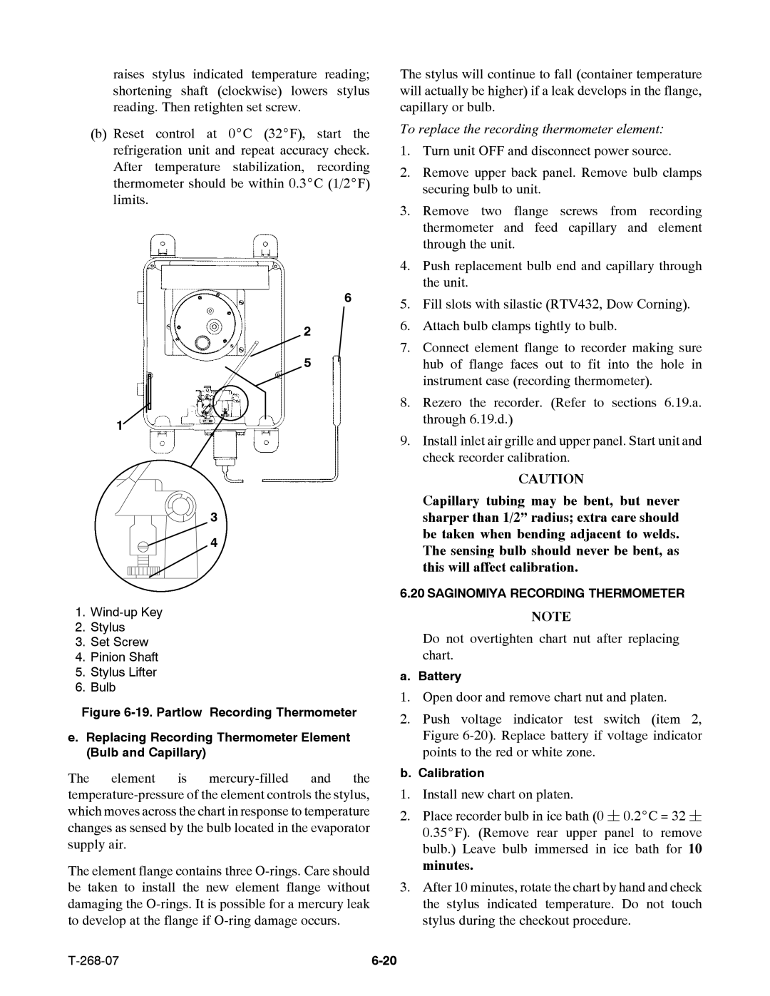
1.
2.Stylus
3.Set Screw
4.Pinion Shaft
5.Stylus Lifter
6.Bulb
Figure 6-19. Partlow Recording Thermometer
e.Replacing Recording Thermometer Element (Bulb and Capillary)
The element is
The element flange contains three
The stylus will continue to fall (container temperature will actually be higher) if a leak develops in the flange, capillary or bulb.
To replace the recording thermometer element:
1.Turn unit OFF and disconnect power source.
2.Remove upper back panel. Remove bulb clamps securing bulb to unit.
3.Remove two flange screws from recording thermometer and feed capillary and element through the unit.
4.Push replacement bulb end and capillary through the unit.
5.Fill slots with silastic (RTV432, Dow Corning).
6.Attach bulb clamps tightly to bulb.
7.Connect element flange to recorder making sure hub of flange faces out to fit into the hole in instrument case (recording thermometer).
8.Rezero the recorder. (Refer to sections 6.19.a. through 6.19.d.)
9.Install inlet air grille and upper panel. Start unit and check recorder calibration.
CAUTION
Capillary tubing may be bent, but never sharper than 1/2” radius; extra care should be taken when bending adjacent to welds. The sensing bulb should never be bent, as this will affect calibration.
6.20 SAGINOMIYA RECORDING THERMOMETER
NOTE
Do not overtighten chart nut after replacing chart.
a. Battery
1.Open door and remove chart nut and platen.
2.Push voltage indicator test switch (item 2, Figure
b. Calibration
1.Install new chart on platen.
2.Place recorder bulb in ice bath (0 ¦ 0.2_C = 32 ¦ 0.35_F). (Remove rear upper panel to remove bulb.) Leave bulb immersed in ice bath for 10 minutes.
3.After 10 minutes, rotate the chart by hand and check the stylus indicated temperature. Do not touch stylus during the checkout procedure.
|