SECTION 6
SERVICE
NOTE
To avoid damage to the earth’s ozone layer, use a refrigerant recovery system whenever removing refrigerant. When working with refrigerants you must comply with all local government environmental laws. In the U.S.A., refer to EPA section 608.
6.1 MANIFOLD GAUGE SET
The manifold gauge set can be used to determine system operating pressure, add a refrigerant charge, and to equalize or evacuate the system.
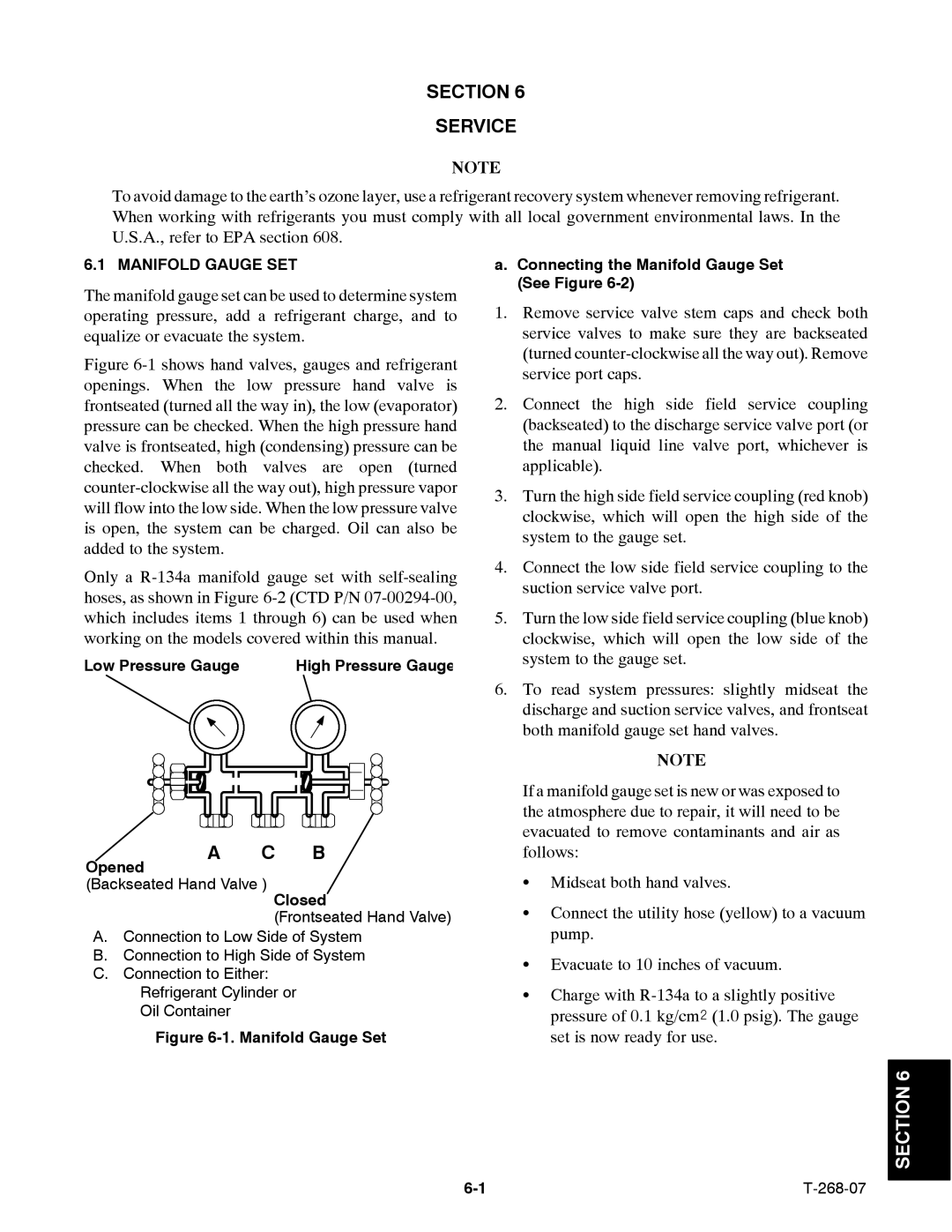
Figure 6-1 shows hand valves, gauges and refrigerant openings. When the low pressure hand valve is frontseated (turned all the way in), the low (evaporator) pressure can be checked. When the high pressure hand valve is frontseated, high (condensing) pressure can be checked. When both valves are open (turned counter-clockwise all the way out), high pressure vapor will flow into the low side. When the low pressure valve is open, the system can be charged. Oil can also be added to the system.
Only a R-134a manifold gauge set with self-sealing hoses, as shown in Figure 6-2 (CTD P/N 07-00294-00, which includes items 1 through 6) can be used when working on the models covered within this manual.
Low Pressure Gauge | High Pressure Gauge |
a.Connecting the Manifold Gauge Set (See Figure
1.Remove service valve stem caps and check both service valves to make sure they are backseated (turned
2.Connect the high side field service coupling (backseated) to the discharge service valve port (or the manual liquid line valve port, whichever is applicable).
3.Turn the high side field service coupling (red knob) clockwise, which will open the high side of the system to the gauge set.
4.Connect the low side field service coupling to the suction service valve port.
5.Turn the low side field service coupling (blue knob) clockwise, which will open the low side of the system to the gauge set.
6.To read system pressures: slightly midseat the discharge and suction service valves, and frontseat both manifold gauge set hand valves.
NOTE
Opened
A C B
If a manifold gauge set is new or was exposed to the atmosphere due to repair, it will need to be evacuated to remove contaminants and air as follows:
(Backseated Hand Valve )
Closed
(Frontseated Hand Valve)
A.Connection to Low Side of System
B.Connection to High Side of System
C.Connection to Either:
Refrigerant Cylinder or
Oil Container
Figure 6-1. Manifold Gauge Set
SConnect the utility hose (yellow) to a vacuum pump.
SEvacuate to 10 inches of vacuum.
SCharge with