The DataCORDER alarms for the USDA and cargo probes are configurable using the interrogation program or via a configuration card. There are four configuration variables for the DataCORDER, which are listed in Table
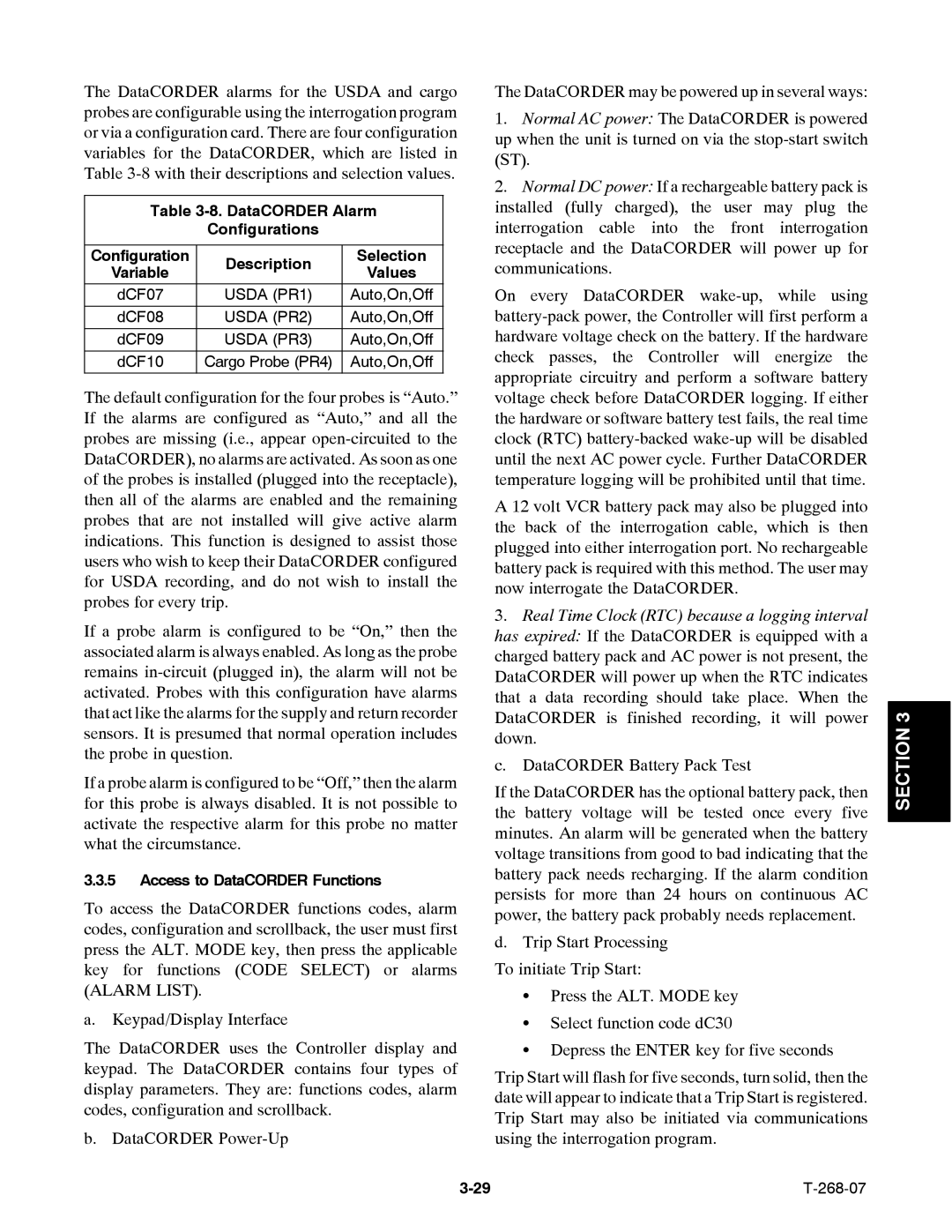
Table 3-8. DataCORDER Alarm
Configurations
Configuration | Description | Selection | |
Variable | Values | ||
| |||
|
|
| |
dCF07 | USDA (PR1) | Auto,On,Off | |
|
|
| |
dCF08 | USDA (PR2) | Auto,On,Off | |
|
|
| |
dCF09 | USDA (PR3) | Auto,On,Off | |
dCF10 | Cargo Probe (PR4) | Auto,On,Off |
The default configuration for the four probes is “Auto.” If the alarms are configured as “Auto,” and all the probes are missing (i.e., appear
If a probe alarm is configured to be “On,” then the associated alarm is always enabled. As long as the probe remains
If a probe alarm is configured to be “Off,” then the alarm for this probe is always disabled. It is not possible to activate the respective alarm for this probe no matter what the circumstance.
3.3.5Access to DataCORDER Functions
To access the DataCORDER functions codes, alarm codes, configuration and scrollback, the user must first press the ALT. MODE key, then press the applicable key for functions (CODE SELECT) or alarms (ALARM LIST).
a. Keypad/Display Interface
The DataCORDER uses the Controller display and keypad. The DataCORDER contains four types of display parameters. They are: functions codes, alarm codes, configuration and scrollback.
b. DataCORDER
The DataCORDER may be powered up in several ways:
1.Normal AC power: The DataCORDER is powered up when the unit is turned on via the
2.Normal DC power: If a rechargeable battery pack is installed (fully charged), the user may plug the interrogation cable into the front interrogation receptacle and the DataCORDER will power up for communications.
On every DataCORDER
A 12 volt VCR battery pack may also be plugged into the back of the interrogation cable, which is then plugged into either interrogation port. No rechargeable battery pack is required with this method. The user may now interrogate the DataCORDER.
3.Real Time Clock (RTC) because a logging interval has expired: If the DataCORDER is equipped with a charged battery pack and AC power is not present, the DataCORDER will power up when the RTC indicates that a data recording should take place. When the DataCORDER is finished recording, it will power down.
c. DataCORDER Battery Pack Test
If the DataCORDER has the optional battery pack, then the battery voltage will be tested once every five minutes. An alarm will be generated when the battery voltage transitions from good to bad indicating that the battery pack needs recharging. If the alarm condition persists for more than 24 hours on continuous AC power, the battery pack probably needs replacement.
d.Trip Start Processing To initiate Trip Start:
S Press the ALT. MODE key
SSelect function code dC30
SDepress the ENTER key for five seconds
Trip Start will flash for five seconds, turn solid, then the date will appear to indicate that a Trip Start is registered. Trip Start may also be initiated via communications using the interrogation program.