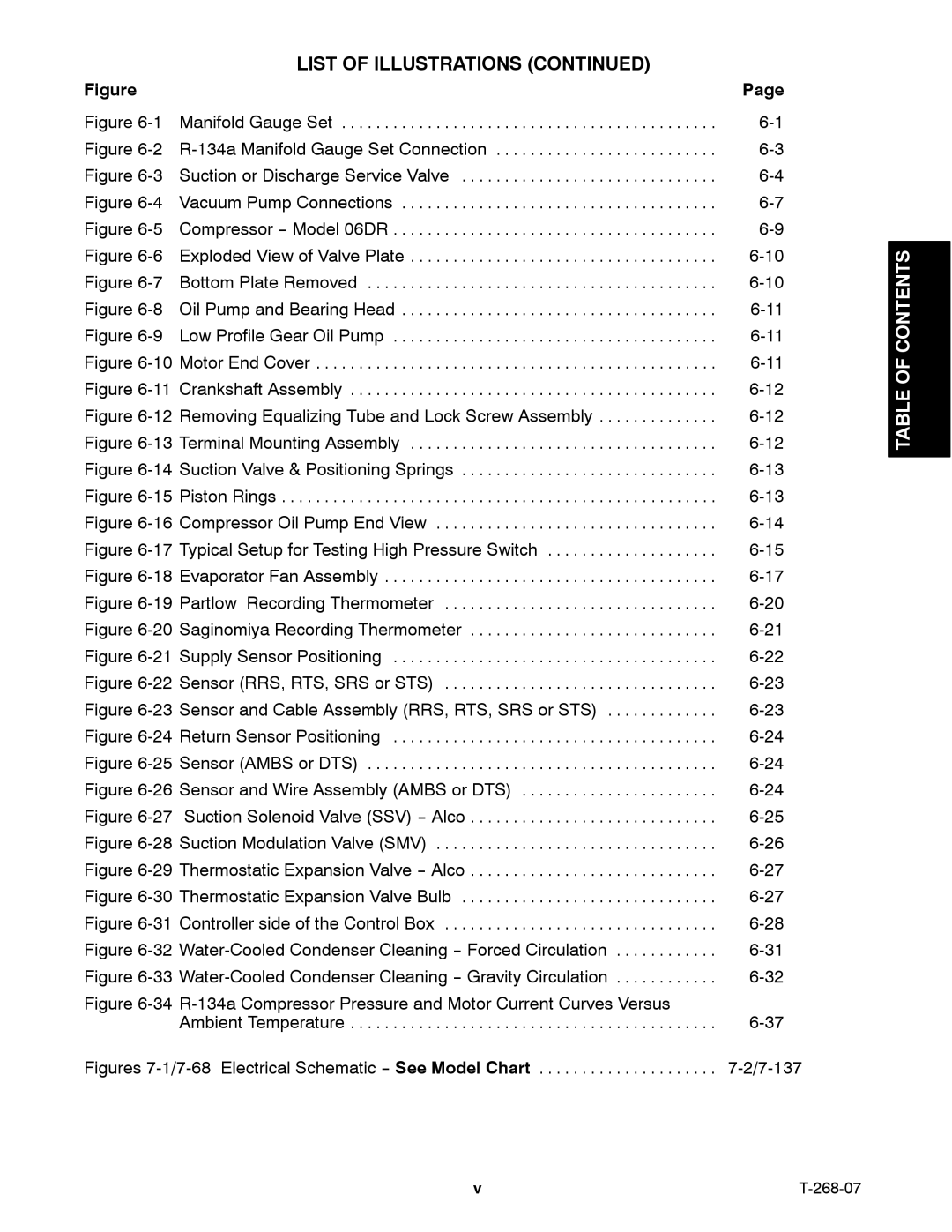
LIST OF ILLUSTRATIONS (CONTINUED)
Figure |
| Page |
Figure | Manifold Gauge Set | |
Figure |
| |
Figure | Suction or Discharge Service Valve | |
Figure | Vacuum Pump Connections | |
Figure | Compressor | |
Figure | Exploded View of Valve Plate | |
Figure | Bottom Plate Removed | |
Figure | Oil Pump and Bearing Head | |
Figure | Low Profile Gear Oil Pump | |
Figure | Motor End Cover | |
Figure | Crankshaft Assembly | |
Figure | Removing Equalizing Tube and Lock Screw Assembly | |
Figure | Terminal Mounting Assembly | |
Figure | Suction Valve & Positioning Springs | |
Figure | Piston Rings | |
Figure | Compressor Oil Pump End View | |
Figure | Typical Setup for Testing High Pressure Switch | |
Figure | Evaporator Fan Assembly | |
Figure | Partlow Recording Thermometer | |
Figure | Saginomiya Recording Thermometer | |
Figure | Supply Sensor Positioning | |
Figure | Sensor (RRS, RTS, SRS or STS) | |
Figure | Sensor and Cable Assembly (RRS, RTS, SRS or STS) | |
Figure | Return Sensor Positioning | |
Figure | Sensor (AMBS or DTS) | |
Figure | Sensor and Wire Assembly (AMBS or DTS) | |
Figure | ||
Figure | Suction Modulation Valve (SMV) | |
Figure | Thermostatic Expansion Valve | |
Figure | Thermostatic Expansion Valve Bulb | |
Figure | Controller side of the Control Box | |
Figure | ||
Figure | ||
Figure |
| |
| Ambient Temperature | |
Figures | ||
TABLE OF CONTENTS
v |
