8
6
7
|
| 5 |
3 |
| 4 |
|
| |
| 2 | 19 |
|
| |
|
| 18 |
|
| 1 |
9 |
17 |
16
10
11
12
13
SECTION 2
|
|
| 15 | 14 |
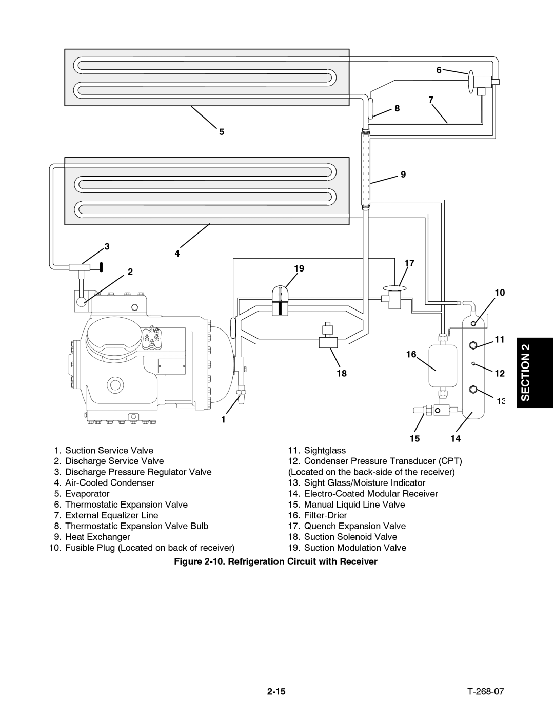
1. | Suction Service Valve | 11. | Sightglass |
|
2. | Discharge Service Valve | 12. | Condenser Pressure Transducer (CPT) | |
3. | Discharge Pressure Regulator Valve | (Located on the | ||
4. | 13. | Sight Glass/Moisture Indicator |
| |
5. | Evaporator | 14. |
| |
6. | Thermostatic Expansion Valve | 15. | Manual Liquid Line Valve |
|
7. | External Equalizer Line | 16. |
| |
8. | Thermostatic Expansion Valve Bulb | 17. | Quench Expansion Valve |
|
9. | Heat Exchanger | 18. | Suction Solenoid Valve |
|
10. | Fusible Plug (Located on back of receiver) | 19. | Suction Modulation Valve |
|
Figure 2-10. Refrigeration Circuit with Receiver
|