LIST OF TABLES
Table |
|
|
| Page |
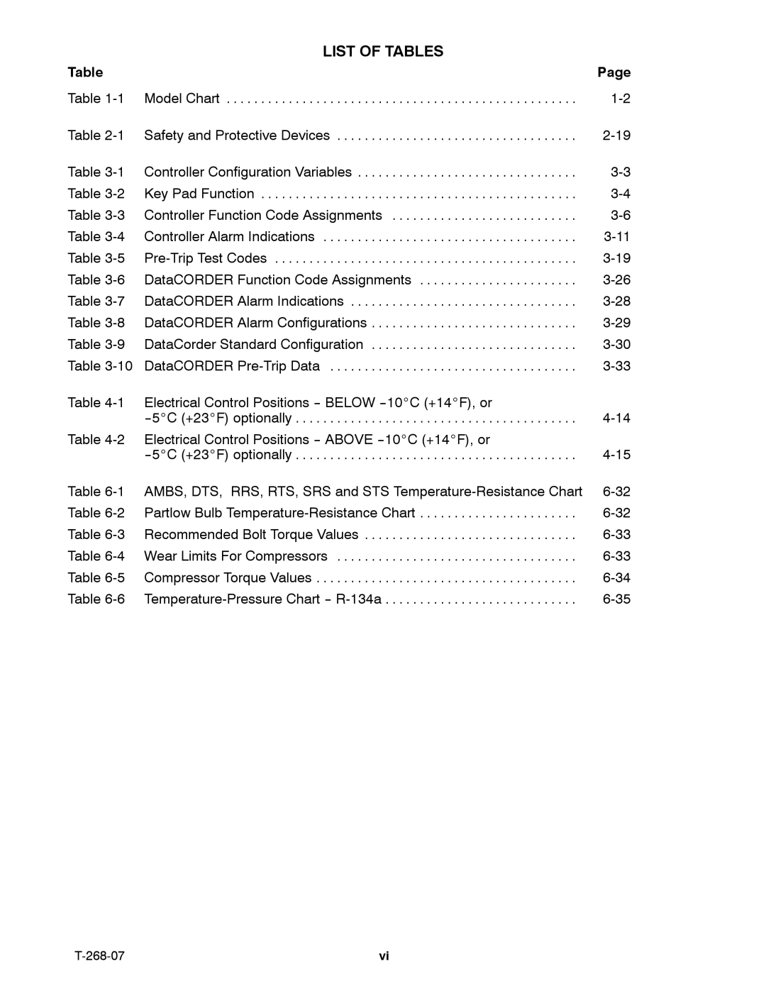
Table | Model Chart | . . . . . . . . . | . . . . . . . . . . . . . . . . . . . . . . . . . . . . | |
Table | Safety and Protective Devices | . . . . . . . . . . . . . . . . . . . . . . . . . . . . | ||
Table | Controller Configuration Variables . . . . | . . . . . . . . . . . . . . . . . . . . . . . . . . . . | ||
Table | Key Pad Function | . . . . . . . . . | . . . . . . . . . . . . . . . . . . . . . . . . . . . . | |
Table | Controller Function Code Assignments | . . . . . . . . . . . . . . . . . . . . . . . . . . . | ||
Table | Controller Alarm Indications | . . . . . . . . . | . . . . . . . . . . . . . . . . . . . . . . . . . . . . | |
Table | . . . . . . . . . | . . . . . . . . . . . . . . . . . . . . . . . . . . . . | ||
Table | DataCORDER Function Code Assignments | |||
Table | DataCORDER Alarm Indications | . . . . . . . . . . . . . . . . . . . . . . . . . . . . | ||
Table | DataCORDER Alarm Configurations . . | . . . . . . . . . . . . . . . . . . . . . . . . . . . . | ||
Table | DataCorder Standard Configuration . . | . . . . . . . . . . . . . . . . . . . . . . . . . . . . | ||
Table | DataCORDER | . . . . . . . . | . . . . . . . . . . . . . . . . . . . . . . . . . . . . | |
Table | Electrical Control Positions | BELOW | 10_C (+14_F), or |
|
| . . . . . . . . . | . . . . . . . . . . . . . . . . . . . . . . . . . . . . | ||
Table | Electrical Control Positions | ABOVE | 10_C (+14_F), or |
|
| . . . . . . . . . | . . . . . . . . . . . . . . . . . . . . . . . . . . . . | ||
Table | AMBS, DTS, RRS, RTS, SRS and STS | |||
Table | Partlow Bulb | |||
Table | Recommended Bolt Torque Values . . . | . . . . . . . . . . . . . . . . . . . . . . . . . . . . | ||
Table | Wear Limits For Compressors | . . . . . . . . . . . . . . . . . . . . . . . . . . . . | ||
Table | Compressor Torque Values . | . . . . . . . . . | . . . . . . . . . . . . . . . . . . . . . . . . . . . . | |
Table | . . . . . . . . . . . . . . . . . . . . . . . . . . . . | |||
vi |