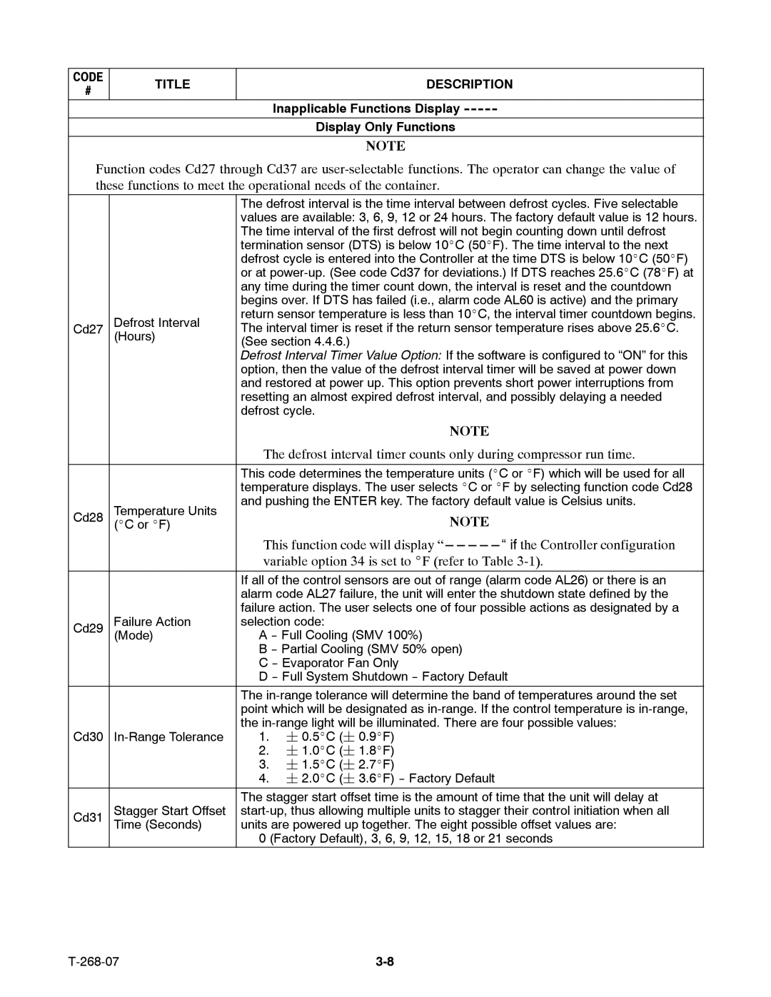
CODE | TITLE | DESCRIPTION | |
# | |||
|
| ||
|
| Inapplicable Functions Display | |
|
| Display Only Functions | |
|
|
| |
|
| NOTE |
Function codes Cd27 through Cd37 are
|
| The defrost interval is the time interval between defrost cycles. Five selectable | ||
|
| values are available: 3, 6, 9, 12 or 24 hours. The factory default value is 12 hours. | ||
|
| The time interval of the first defrost will not begin counting down until defrost | ||
|
| termination sensor (DTS) is below 10_C (50_F). The time interval to the next | ||
|
| defrost cycle is entered into the Controller at the time DTS is below 10_C (50_F) | ||
|
| or at | ||
|
| any time during the timer count down, the interval is reset and the countdown | ||
|
| begins over. If DTS has failed (i.e., alarm code AL60 is active) and the primary | ||
| Defrost Interval | return sensor temperature is less than 10_C, the interval timer countdown begins. | ||
Cd27 | The interval timer is reset if the return sensor temperature rises above 25.6_C. | |||
(Hours) | ||||
(See section 4.4.6.) | ||||
|
| |||
|
| Defrost Interval Timer Value Option: If the software is configured to “ON” for this | ||
|
| option, then the value of the defrost interval timer will be saved at power down | ||
|
| and restored at power up. This option prevents short power interruptions from | ||
|
| resetting an almost expired defrost interval, and possibly delaying a needed | ||
|
| defrost cycle. | ||
|
|
| NOTE | |
|
| The defrost interval timer counts only during compressor run time. | ||
|
|
| ||
|
| This code determines the temperature units (_C or _F) which will be used for all | ||
|
| temperature displays. The user selects _C or _F by selecting function code Cd28 | ||
| Temperature Units | and pushing the ENTER key. The factory default value is Celsius units. | ||
Cd28 |
| NOTE | ||
(_C or _F) |
| |||
|
| This function code will display | ||
|
| variable option 34 is set to _F (refer to Table | ||
|
| If all of the control sensors are out of range (alarm code AL26) or there is an | ||
|
| alarm code AL27 failure, the unit will enter the shutdown state defined by the | ||
|
| failure action. The user selects one of four possible actions as designated by a | ||
Cd29 | Failure Action | selection code: | ||
(Mode) | A | |||
|
| B | ||
|
| C | ||
|
| D | ||
|
| The | ||
|
| point which will be designated as | ||
|
| the | ||
Cd30 | 1. | ¦ 0.5_C (¦ 0.9_F) | ||
|
| 2. | ¦ 1.0_C (¦ 1.8_F) | |
|
| 3. | ¦ 1.5_C (¦ 2.7_F) | |
|
| 4. ¦ 2.0_C (¦ 3.6_F) | ||
|
| The stagger start offset time is the amount of time that the unit will delay at | ||
Cd31 | Stagger Start Offset | |||
| Time (Seconds) | units are powered up together. The eight possible offset values are: | ||
|
| 0 (Factory Default), 3, 6, 9, 12, 15, 18 or 21 seconds | ||
