CODE | TITLE | DESCRIPTION | |
# | |||
|
| ||
|
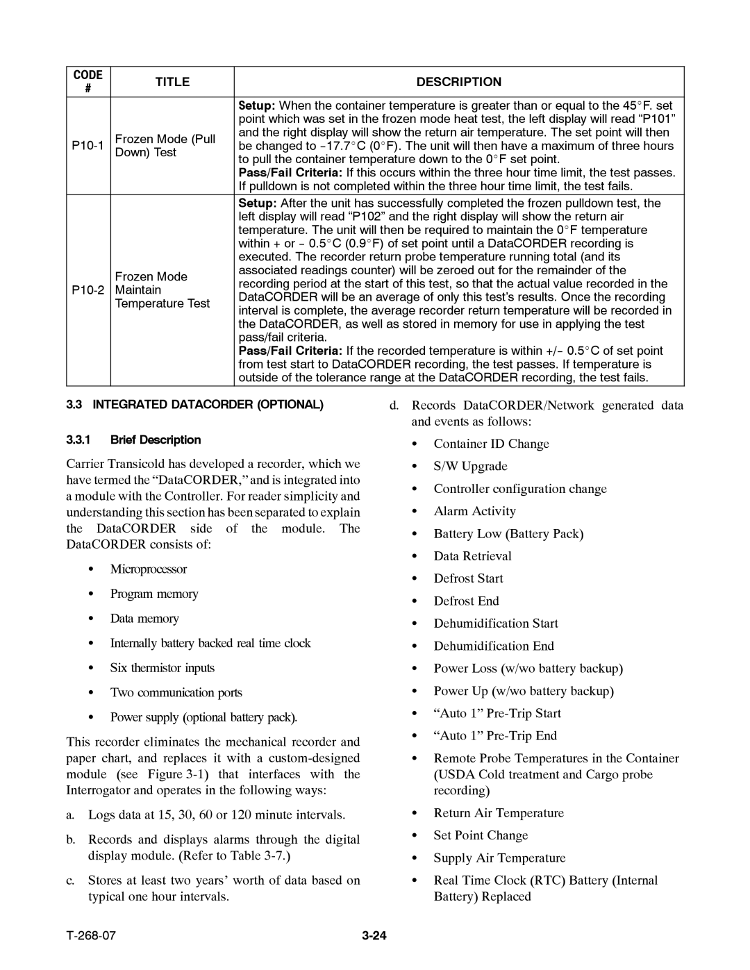
| Setup: When the container temperature is greater than or equal to the 45_F. set | |
|
| point which was set in the frozen mode heat test, the left display will read “P101” | |
Frozen Mode (Pull | and the right display will show the return air temperature. The set point will then | ||
be changed to | |||
| Down) Test | to pull the container temperature down to the 0_F set point. | |
|
| Pass/Fail Criteria: If this occurs within the three hour time limit, the test passes. | |
|
| If pulldown is not completed within the three hour time limit, the test fails. | |
|
| Setup: After the unit has successfully completed the frozen pulldown test, the | |
|
| left display will read “P102” and the right display will show the return air | |
|
| temperature. The unit will then be required to maintain the 0_F temperature | |
|
| within + or | |
|
| executed. The recorder return probe temperature running total (and its | |
| Frozen Mode | associated readings counter) will be zeroed out for the remainder of the | |
| recording period at the start of this test, so that the actual value recorded in the | ||
Maintain | |||
DataCORDER will be an average of only this test’s results. Once the recording | |||
| Temperature Test | ||
| interval is complete, the average recorder return temperature will be recorded in | ||
|
| ||
|
| the DataCORDER, as well as stored in memory for use in applying the test | |
|
| pass/fail criteria. | |
|
| Pass/Fail Criteria: If the recorded temperature is within | |
|
| from test start to DataCORDER recording, the test passes. If temperature is | |
|
| outside of the tolerance range at the DataCORDER recording, the test fails. |
3.3 | INTEGRATED DATACORDER (OPTIONAL) |
| d. Records DataCORDER/Network generated data | |||||
|
|
|
|
|
| and events as follows: | ||
3.3.1 | Brief Description |
|
|
| S | Container ID Change | ||
Carrier Transicold has developed a recorder, which we | S | S/W Upgrade | ||||||
have termed the “DataCORDER,” and is integrated into | S | Controller configuration change | ||||||
a module with the Controller. For reader simplicity and | ||||||||
| Alarm Activity | |||||||
understanding this section has been separated to explain | S | |||||||
the |
| DataCORDER side | of | the module. | The | S | Battery Low (Battery Pack) | |
DataCORDER consists of: |
|
|
| |||||
|
|
| S | Data Retrieval | ||||
| S | Microprocessor |
|
|
| |||
|
|
|
| S | Defrost Start | |||
|
| Program memory |
|
|
| |||
| S |
|
|
| S | Defrost End | ||
|
|
|
|
|
| |||
| S | Data memory |
|
|
| S | Dehumidification Start | |
|
|
|
|
|
| |||
| S Internally battery backed real time clock |
| S | Dehumidification End | ||||
| S | Six thermistor inputs |
|
|
| S | Power Loss (w/wo battery backup) | |
| S | Two communication ports |
|
| S | Power Up (w/wo battery backup) | ||
| S Power supply (optional battery pack). |
| S | “Auto 1” | ||||
This recorder eliminates the mechanical recorder and | S “Auto 1” | |||||||
|
| |||||||
paper chart, and replaces it with a | S | Remote Probe Temperatures in the Container | ||||||
module (see Figure | that | interfaces with | the |
| (USDA Cold treatment and Cargo probe | |||
Interrogator and operates in the following ways: |
|
| recording) | |||||
a. | Logs data at 15, 30, 60 or 120 minute intervals. | S | Return Air Temperature | |||||
b. | Records and displays alarms through the digital | S | Set Point Change | |||||
|
| |||||||
| display module. (Refer to Table |
| S | Supply Air Temperature | ||||
c. | Stores at least two years’ worth of data based on | S | Real Time Clock (RTC) Battery (Internal | |||||
| typical one hour intervals. |
|
|
| Battery) Replaced | |||