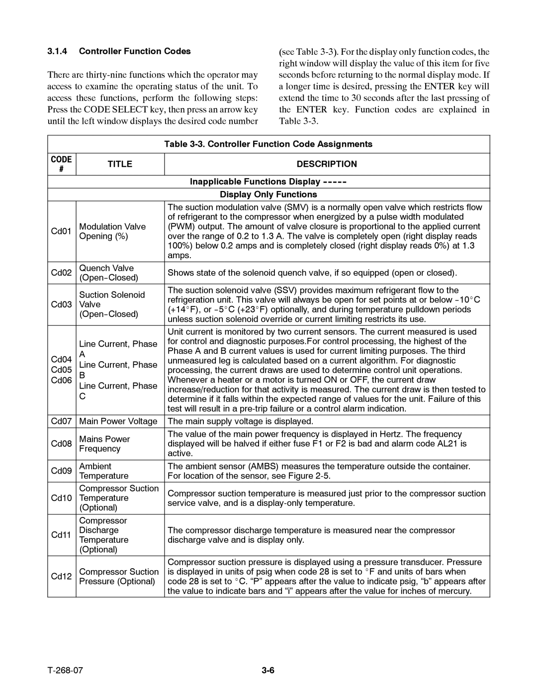
3.1.4Controller Function Codes
There are
(see Table
|
| Table | |
|
|
| |
CODE | TITLE | DESCRIPTION | |
# | |||
|
| ||
|
| Inapplicable Functions Display | |
|
| Display Only Functions | |
|
|
| |
|
| The suction modulation valve (SMV) is a normally open valve which restricts flow | |
|
| of refrigerant to the compressor when energized by a pulse width modulated | |
Cd01 | Modulation Valve | (PWM) output. The amount of valve closure is proportional to the applied current | |
| Opening (%) | over the range of 0.2 to 1.3 A. The valve is completely open (right display reads | |
|
| 100%) below 0.2 amps and is completely closed (right display reads 0%) at 1.3 | |
|
| amps. | |
Cd02 | Quench Valve | Shows state of the solenoid quench valve, if so equipped (open or closed). | |
|
| ||
| Suction Solenoid | The suction solenoid valve (SSV) provides maximum refrigerant flow to the | |
| refrigeration unit. This valve will always be open for set points at or below | ||
Cd03 | Valve | ||
(+14_F), or | |||
| |||
| unless suction solenoid override or current limiting restricts its use. | ||
|
| ||
|
|
| |
|
| Unit current is monitored by two current sensors. The current measured is used | |
| Line Current, Phase | for control and diagnostic purposes.For control processing, the highest of the | |
| Phase A and B current values is used for current limiting purposes. The third | ||
Cd04 | A | ||
unmeasured leg is calculated based on a current algorithm. For diagnostic | |||
Cd05 | Line Current, Phase | processing, the current draws are used to determine control unit operations. | |
Cd06 | B | Whenever a heater or a motor is turned ON or OFF, the current draw | |
| Line Current, Phase | increase/reduction for that activity is measured. The current draw is then tested to | |
| C | ||
| determine if it falls within the expected range of values for the unit. Failure of this | ||
|
| test will result in a | |
Cd07 | Main Power Voltage | The main supply voltage is displayed. | |
|
|
| |
| Mains Power | The value of the main power frequency is displayed in Hertz. The frequency | |
Cd08 | displayed will be halved if either fuse F1 or F2 is bad and alarm code AL21 is | ||
| Frequency | active. | |
|
| ||
|
|
| |
Cd09 | Ambient | The ambient sensor (AMBS) measures the temperature outside the container. | |
| Temperature | For location of the sensor, see Figure | |
Cd10 | Compressor Suction | Compressor suction temperature is measured just prior to the compressor suction | |
Temperature | service valve, and is a | ||
| (Optional) | ||
|
| ||
| Compressor |
| |
Cd11 | Discharge | The compressor discharge temperature is measured near the compressor | |
| Temperature | discharge valve and is display only. | |
| (Optional) |
| |
|
| Compressor suction pressure is displayed using a pressure transducer. Pressure | |
Cd12 | Compressor Suction | is displayed in units of psig when code 28 is set to _F and units of bars when | |
| Pressure (Optional) | code 28 is set to _C. “P” appears after the value to indicate psig, “b” appears after | |
|
| the value to indicate bars and “i” appears after the value for inches of mercury. |