suction service valve flange cavity or by removing the oil fill plug. (See Figure
d. To Remove Oil From an 06DR Compressor:
1.If the oil level recorded in step a.3 is above
2.Close (frontseat) suction service valve and pump unit down to 1.2 to 1.3 kg/cm@ (2 to 4 psig). Frontseat discharge service valve and slowly bleed remaining refrigerant.
3.Remove the oil drain plug on the bottom plate of the compressor and drain the proper amount of oil from the compressor to obtain the correct level (maximum is
DO NOT FORGET TO OPEN SUCTION AND DISCHARGE SERVICE VALVES.
4.Repeat step (a) to ensure proper oil level.
6.11 FILTER-DRIER
On units equipped with a
6.12 HIGH PRESSURE SWITCH
6.12.1 Replacing High Pressure Switch
a.Turn unit
b.Disconnect wiring from defective switch. The high pressure switch is located on the center head and is removed by turning counterclockwise. (See Figure
c.Install a new high pressure switch after verifying switch settings. (Refer to section 6.12.2.)
d.Evacuate and dehydrate the compressor per section 6.5.1.
6.12.2Checking High Pressure Switch
WARNING
Do not use a nitrogen cylinder without a pressure regulator. Do not use oxygen in or near a refrigeration system as an explosion may occur.
NOTE
The high pressure switch (HPS) is
a.Remove switch as outlined in section 6.12.1.
b.Connect ohmmeter or continuity light across switch terminals. Ohm meter will indicate no resistance or continuity light will be illuminated if the switch closed after relieving compressor pressure.
To Check Filter-Drier:
a. Test for a restricted or plugged |
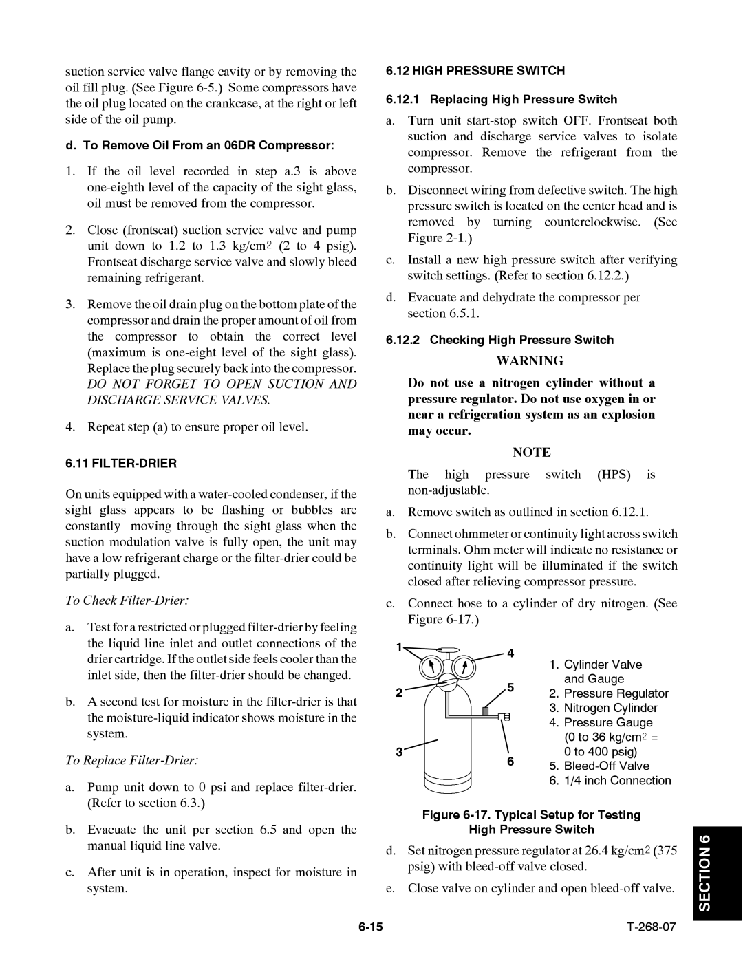
c.Connect hose to a cylinder of dry nitrogen. (See Figure
the liquid line inlet and outlet connections of the |
drier cartridge. If the outlet side feels cooler than the |
inlet side, then the |
b. A second test for moisture in the |
the |
system. |
To Replace Filter-Drier:
a. Pump unit down to 0 psi and replace |
(Refer to section 6.3.) |
1
2
3
4
5
6
1.Cylinder Valve and Gauge
2.Pressure Regulator
3.Nitrogen Cylinder
4.Pressure Gauge (0 to 36 kg/cm@ = 0 to 400 psig)
5.
6.1/4 inch Connection
b. | Evacuate the unit per section 6.5 and open the |
| manual liquid line valve. |
c. | After unit is in operation, inspect for moisture in |
| system. |
Figure 6-17. Typical Setup for Testing
High Pressure Switch
d.Set nitrogen pressure regulator at 26.4 kg/cm@ (375 psig) with
e.Close valve on cylinder and open