Table
a.Place the compressor in a position where it will be convenient to drain the oil. Remove the oil plug on the oil pump inlet passage (see Figure
b.Remove cylinder head capscrews. If the cylinder head is stuck, tap the center of the cylinder head with a wooden or lead mallet. DO NOT STRIKE THE SIDE OF THE CYLINDER HEAD! Be careful not to drop the head or damage the gasket sealing surface. (See Figure
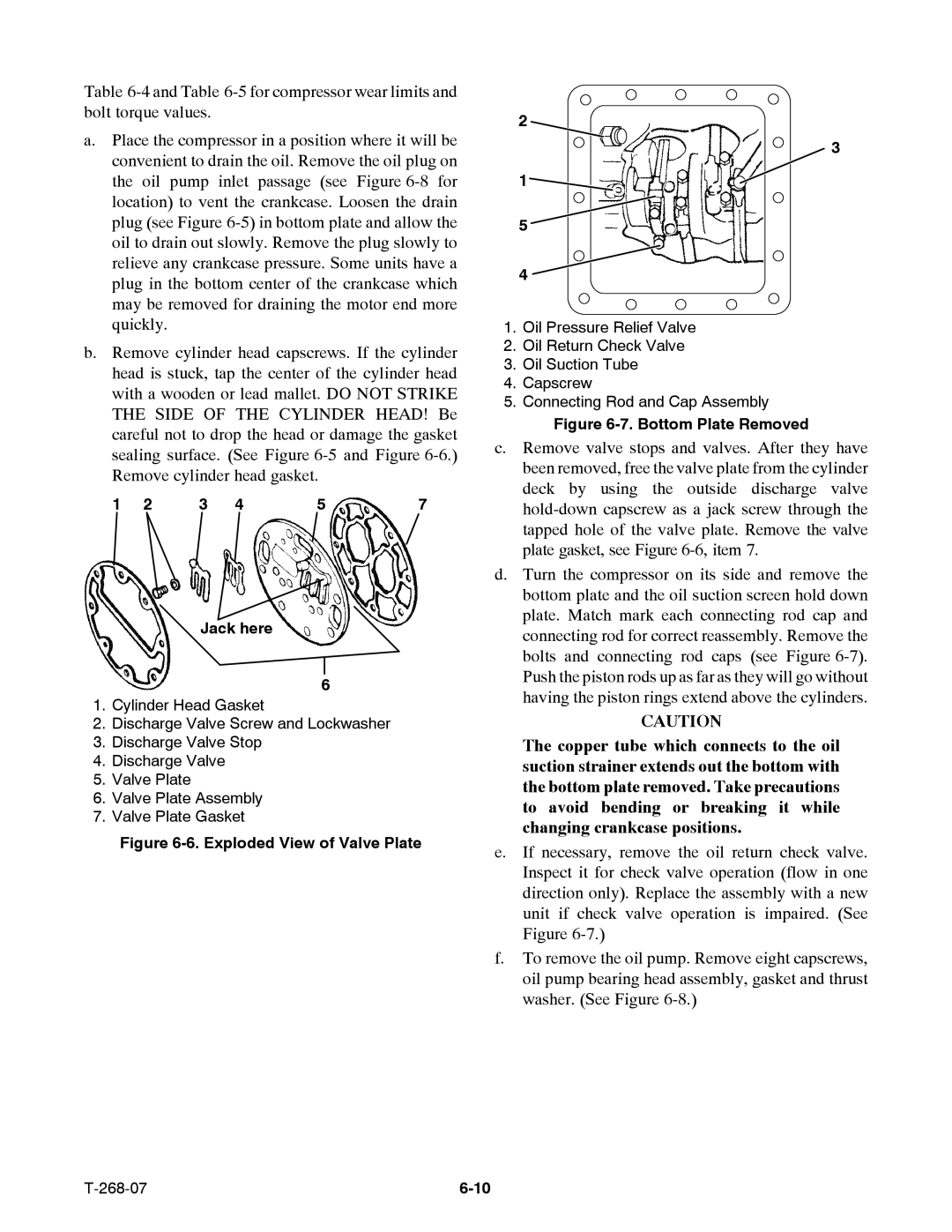
1 | 2 | 3 | 4 | 5 | 7 |
Jack here
6
1.Cylinder Head Gasket
2.Discharge Valve Screw and Lockwasher
3.Discharge Valve Stop
4.Discharge Valve
5.Valve Plate
6.Valve Plate Assembly
7.Valve Plate Gasket
Figure 6-6. Exploded View of Valve Plate
2
![]() 3 1
3 1![]()
![]()
5
4
1.Oil Pressure Relief Valve
2.Oil Return Check Valve
3.Oil Suction Tube
4.Capscrew
5.Connecting Rod and Cap Assembly
Figure 6-7. Bottom Plate Removed
c.Remove valve stops and valves. After they have been removed, free the valve plate from the cylinder deck by using the outside discharge valve
d.Turn the compressor on its side and remove the bottom plate and the oil suction screen hold down plate. Match mark each connecting rod cap and connecting rod for correct reassembly. Remove the bolts and connecting rod caps (see Figure
CAUTION
The copper tube which connects to the oil suction strainer extends out the bottom with the bottom plate removed. Take precautions to avoid bending or breaking it while changing crankcase positions.
e.If necessary, remove the oil return check valve. Inspect it for check valve operation (flow in one direction only). Replace the assembly with a new unit if check valve operation is impaired. (See Figure
f.To remove the oil pump. Remove eight capscrews, oil pump bearing head assembly, gasket and thrust washer. (See Figure
|