3.1.3General Layout of the Controller Section
The
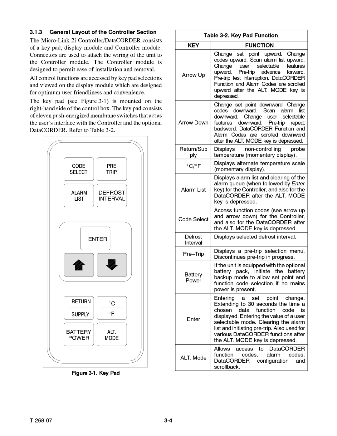
All control functions are accessed by key pad selections and viewed on the display module which are designed for optimum user friendliness and convenience.
The key pad (see Figure
CODE PRE
SELECT TRIP
ALARM DEFROST
LIST INTERVAL
ENTER
RETURN _C
SUPPLY _F
BATTERY ALT.
POWER MODE
Figure 3-1. Key Pad
Table 3-2. Key Pad Function
KEY |
|
| FUNCTION |
|
|
| ||||
|
| |||||||||
| Change set point upward. Change | |||||||||
| codes upward. Scan alarm list upward. | |||||||||
| Change | user | selectable |
| features | |||||
Arrow Up | upward. | advance |
| forward. | ||||||
| ||||||||||
| Function and Alarm Codes are scrolled | |||||||||
| upward after the ALT. MODE key is | |||||||||
| depressed. |
|
|
|
|
|
|
| ||
|
| |||||||||
| Change set point downward. Change | |||||||||
| codes downward. | Scan | alarm | list | ||||||
Arrow Down | downward. | Change | user | selectable | ||||||
features downward. | ||||||||||
| backward. DataCORDER Function and | |||||||||
| Alarm Codes are scrolled downward | |||||||||
| after the ALT. MODE key is depressed. | |||||||||
Return/Sup | Displays |
| probe | |||||||
ply | temperature (momentary display). | |||||||||
_C/_F | Displays alternate temperature scale | |||||||||
(momentary display). |
|
|
| |||||||
|
|
|
| |||||||
| Displays alarm list and clearing of the | |||||||||
| alarm queue (when followed by Enter | |||||||||
Alarm List | key) for the Controller, and also for the | |||||||||
| DataCORDER after the ALT. MODE | |||||||||
| key is depressed. |
|
|
|
|
| ||||
|
| |||||||||
| Access function codes (see arrow up | |||||||||
Code Select | and arrow down) for the Controller, | |||||||||
and also for the DataCORDER after | ||||||||||
| the ALT. MODE key is depressed. | |||||||||
Defrost | Displays selected defrost interval. | |||||||||
Interval |
|
|
|
|
|
|
|
|
| |
Displays | a | selection | menu. | |||||||
Discontinues |
| |||||||||
|
| |||||||||
| If the unit is equipped with the optional | |||||||||
Battery | battery | pack, | initiate the | battery | ||||||
backup mode to allow set point and | ||||||||||
Power | ||||||||||
function code selection if no mains | ||||||||||
| ||||||||||
| power is present. |
|
|
|
|
| ||||
|
| |||||||||
| Entering a set point change. | |||||||||
| Extending to 30 seconds the time a | |||||||||
| chosen data function code is | |||||||||
Enter | displayed. Entering the value of a user | |||||||||
selectable mode. Clearing the alarm | ||||||||||
| ||||||||||
| list and initiating | |||||||||
| various DataCORDER functions after | |||||||||
| the ALT. MODE key is depressed. | |||||||||
| Allows | access |
| to | DataCORDER | |||||
ALT. Mode | function |
| codes, |
| alarm |
| codes, | |||
DataCORDER | configuration | and | ||||||||
| ||||||||||
| scrollback. |
|
|
|
|
|
|
| ||