Set screw must be removed. 1
|
|
| 11 |
| 5 | 6 | 10 |
| 4 |
| |
|
|
| |
2 | 3 |
|
|
|
| 9 | |
1 |
|
| |
|
|
| |
|
| 7 | 8 |
5
2
4 3
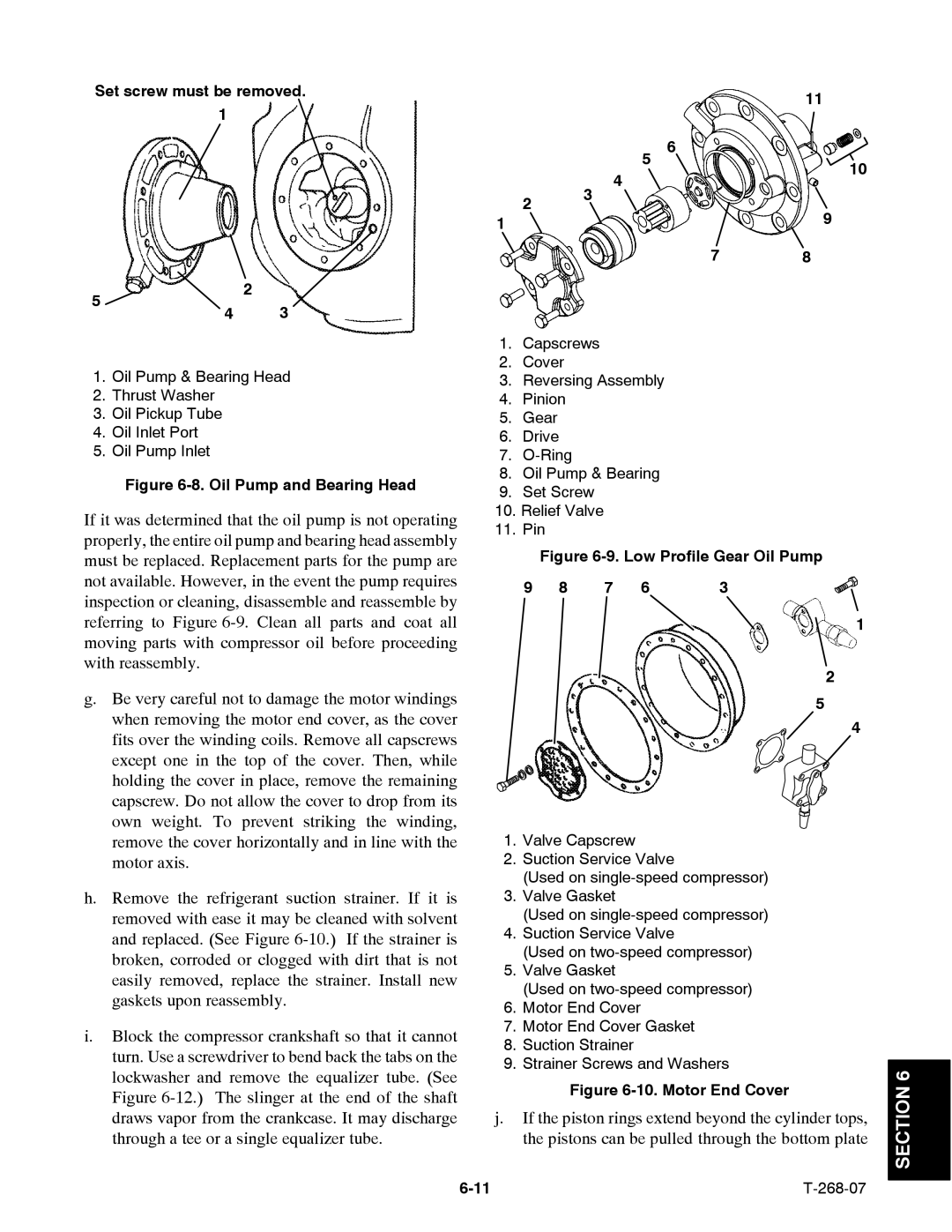
1. Oil Pump & Bearing Head
2. Thrust Washer
3. Oil Pickup Tube
4. Oil Inlet Port
5. Oil Pump Inlet
Figure 6-8. Oil Pump and Bearing Head
If it was determined that the oil pump is not operating properly, the entire oil pump and bearing head assembly must be replaced. Replacement parts for the pump are not available. However, in the event the pump requires inspection or cleaning, disassemble and reassemble by referring to Figure
g.Be very careful not to damage the motor windings when removing the motor end cover, as the cover fits over the winding coils. Remove all capscrews except one in the top of the cover. Then, while holding the cover in place, remove the remaining capscrew. Do not allow the cover to drop from its own weight. To prevent striking the winding, remove the cover horizontally and in line with the motor axis.
h.Remove the refrigerant suction strainer. If it is removed with ease it may be cleaned with solvent and replaced. (See Figure
i.Block the compressor crankshaft so that it cannot turn. Use a screwdriver to bend back the tabs on the lockwasher and remove the equalizer tube. (See Figure
1.Capscrews
2.Cover
3.Reversing Assembly
4.Pinion
5.Gear
6.Drive
7.
8.Oil Pump & Bearing
9.Set Screw
10.Relief Valve
11.Pin
| Figure | |||
9 | 8 | 7 | 6 | 3 |
1
2
5
4
1.Valve Capscrew
2.Suction Service Valve
(Used on
3.Valve Gasket
(Used on
4.Suction Service Valve
(Used on
5.Valve Gasket
(Used on
6.Motor End Cover
7.Motor End Cover Gasket
8.Suction Strainer
9.Strainer Screws and Washers
Figure 6-10. Motor End Cover
j.If the piston rings extend beyond the cylinder tops, the pistons can be pulled through the bottom plate