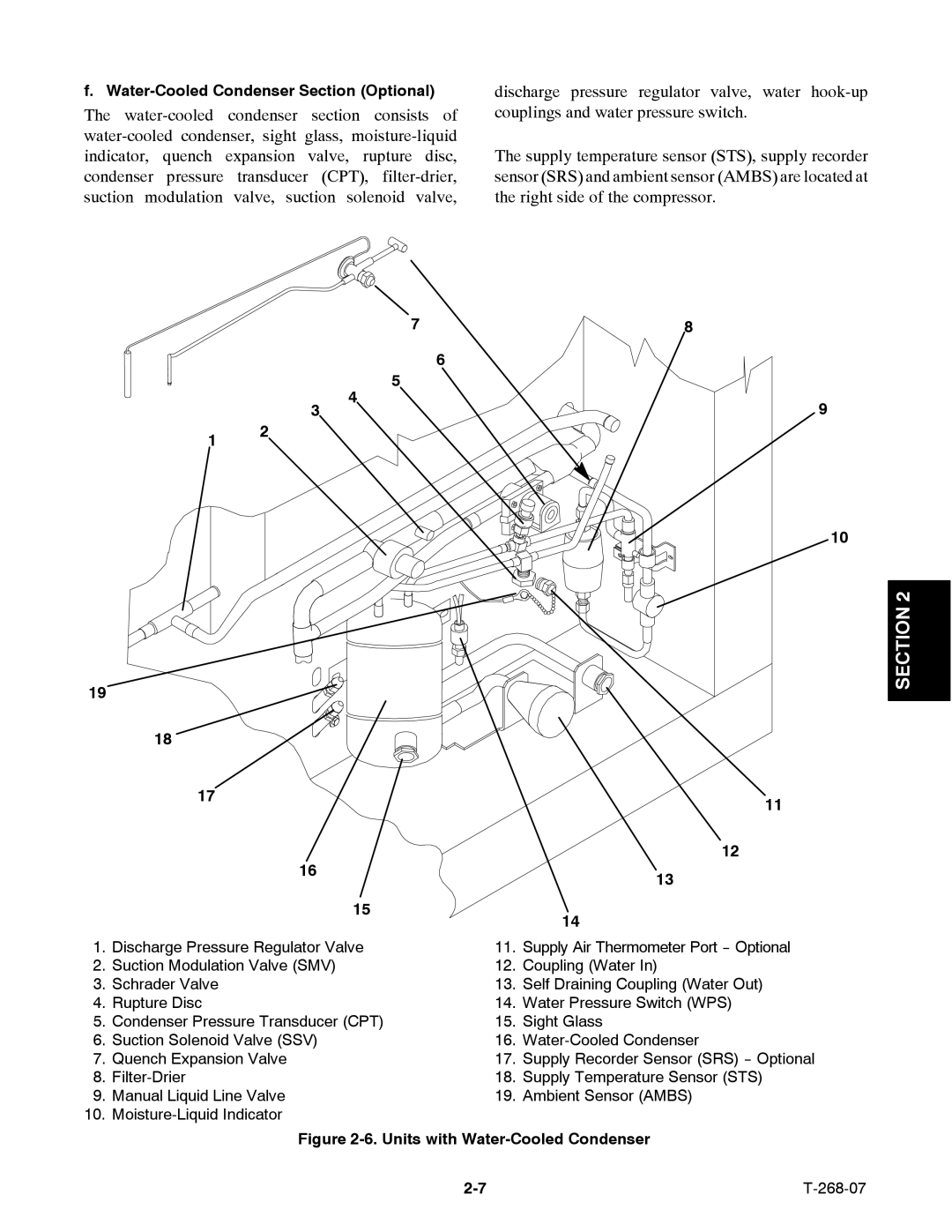
f. Water-Cooled Condenser Section (Optional)
The
discharge pressure regulator valve, water
The supply temperature sensor (STS), supply recorder sensor (SRS) and ambient sensor (AMBS) are located at the right side of the compressor.
3
1 2
19
18
17
16
7
6
5
4
15
8
9
10
11
12
13
14
SECTION 2
1. | Discharge Pressure Regulator Valve | 11. | Supply Air Thermometer Port |
2. | Suction Modulation Valve (SMV) | 12. | Coupling (Water In) |
3. | Schrader Valve | 13. | Self Draining Coupling (Water Out) |
4. | Rupture Disc | 14. | Water Pressure Switch (WPS) |
5. | Condenser Pressure Transducer (CPT) | 15. | Sight Glass |
6. | Suction Solenoid Valve (SSV) | 16. | |
7. | Quench Expansion Valve | 17. | Supply Recorder Sensor (SRS) |
8. | 18. | Supply Temperature Sensor (STS) | |
9. | Manual Liquid Line Valve | 19. | Ambient Sensor (AMBS) |
10. |
|
| |
| Figure | ||
|
| ||