CODE | TITLE | DESCRIPTION |
|
|
# |
|
| ||
|
|
|
| |
|
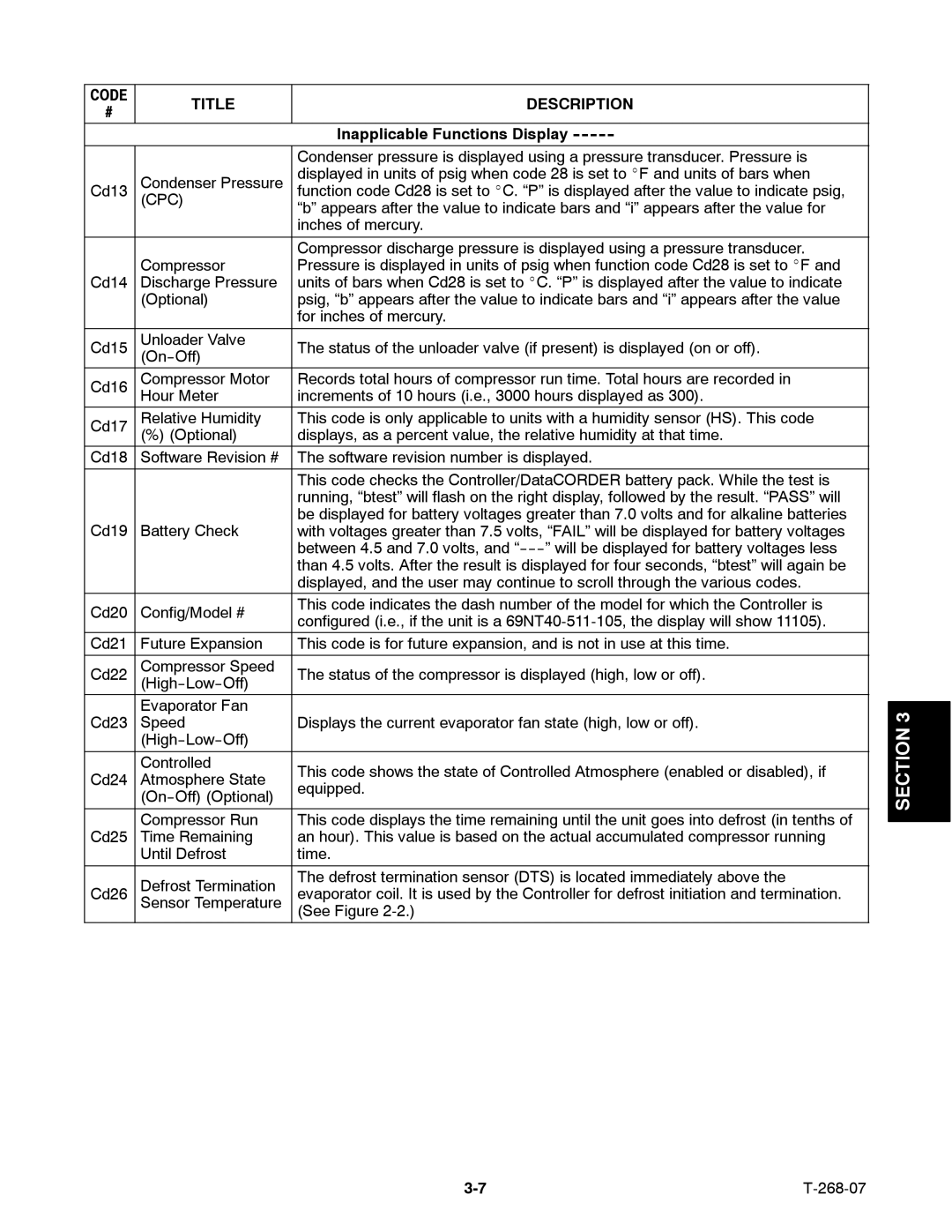
| Inapplicable Functions Display |
|
|
|
| Condenser pressure is displayed using a pressure transducer. Pressure is |
|
|
| Condenser Pressure | displayed in units of psig when code 28 is set to _F and units of bars when |
|
|
Cd13 | function code Cd28 is set to _C. “P” is displayed after the value to indicate psig, |
|
| |
| (CPC) | “b” appears after the value to indicate bars and “i” appears after the value for |
|
|
|
| inches of mercury. |
|
|
|
|
|
|
|
|
| Compressor discharge pressure is displayed using a pressure transducer. |
|
|
| Compressor | Pressure is displayed in units of psig when function code Cd28 is set to _F and |
|
|
Cd14 | Discharge Pressure | units of bars when Cd28 is set to _C. “P” is displayed after the value to indicate |
|
|
| (Optional) | psig, “b” appears after the value to indicate bars and “i” appears after the value |
|
|
|
| for inches of mercury. |
|
|
Cd15 | Unloader Valve | The status of the unloader valve (if present) is displayed (on or off). |
|
|
|
|
|
| |
Cd16 | Compressor Motor | Records total hours of compressor run time. Total hours are recorded in |
|
|
| Hour Meter | increments of 10 hours (i.e., 3000 hours displayed as 300). |
|
|
Cd17 | Relative Humidity | This code is only applicable to units with a humidity sensor (HS). This code |
|
|
| (%) (Optional) | displays, as a percent value, the relative humidity at that time. |
|
|
Cd18 | Software Revision # | The software revision number is displayed. |
|
|
|
|
|
|
|
|
| This code checks the Controller/DataCORDER battery pack. While the test is |
|
|
|
| running, “btest” will flash on the right display, followed by the result. “PASS” will |
|
|
Cd19 | Battery Check | be displayed for battery voltages greater than 7.0 volts and for alkaline batteries |
|
|
with voltages greater than 7.5 volts, “FAIL” will be displayed for battery voltages |
|
| ||
|
| between 4.5 and 7.0 volts, and |
|
|
|
| than 4.5 volts. After the result is displayed for four seconds, “btest” will again be |
|
|
|
| displayed, and the user may continue to scroll through the various codes. |
|
|
Cd20 | Config/Model # | This code indicates the dash number of the model for which the Controller is |
|
|
configured (i.e., if the unit is a |
|
| ||
|
|
|
| |
Cd21 | Future Expansion | This code is for future expansion, and is not in use at this time. |
|
|
|
|
|
|
|
Cd22 | Compressor Speed | The status of the compressor is displayed (high, low or off). |
|
|
|
|
|
| |
| Evaporator Fan |
|
|
|
|
|
| 3 | |
Cd23 | Speed | Displays the current evaporator fan state (high, low or off). |
| |
| SECTION | |||
|
|
| ||
|
|
|
| |
|
|
|
|
|
| Controlled | This code shows the state of Controlled Atmosphere (enabled or disabled), if |
|
|
Cd24 | Atmosphere State |
|
| |
equipped. |
|
| ||
|
|
| ||
|
|
|
| |
|
|
|
|
|
| Compressor Run | This code displays the time remaining until the unit goes into defrost (in tenths of |
|
|
|
| |||
Cd25 | Time Remaining | an hour). This value is based on the actual accumulated compressor running |
|
|
| Until Defrost | time. |
|
|
|
|
|
|
|
| Defrost Termination | The defrost termination sensor (DTS) is located immediately above the |
|
|
Cd26 | evaporator coil. It is used by the Controller for defrost initiation and termination. |
|
| |
| Sensor Temperature | (See Figure |
|
|
|
|
|
|
|
Page 45
Image 45