by holding the spanner wrench stationary and turning the
45
6
3
25
1
7
8
9
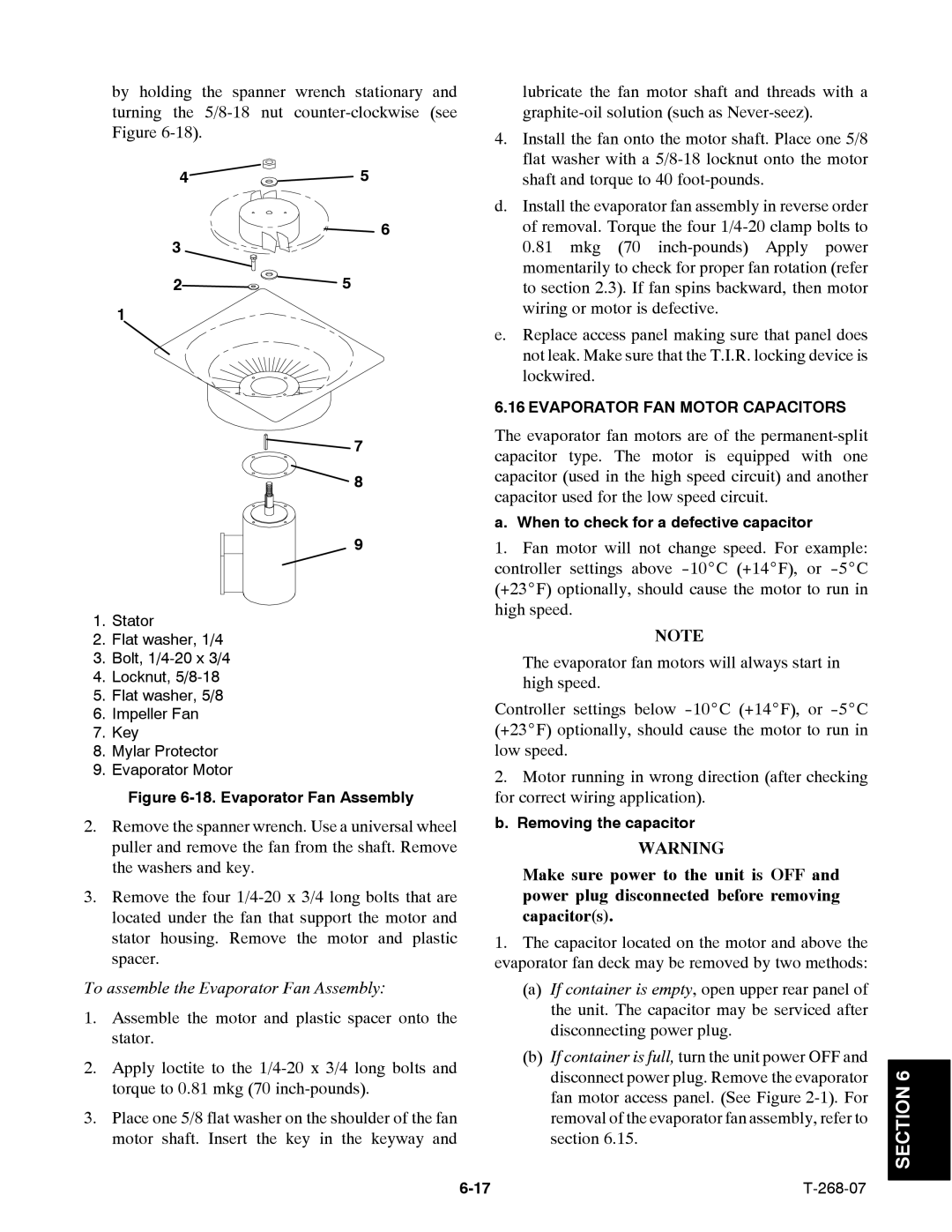
1.Stator
2.Flat washer, 1/4
3.Bolt,
4.Locknut,
5.Flat washer, 5/8
6.Impeller Fan
7.Key
8.Mylar Protector
9.Evaporator Motor
Figure 6-18. Evaporator Fan Assembly
2.Remove the spanner wrench. Use a universal wheel puller and remove the fan from the shaft. Remove the washers and key.
3.Remove the four
To assemble the Evaporator Fan Assembly:
1.Assemble the motor and plastic spacer onto the stator.
2.Apply loctite to the
3.Place one 5/8 flat washer on the shoulder of the fan motor shaft. Insert the key in the keyway and
lubricate the fan motor shaft and threads with a
4.Install the fan onto the motor shaft. Place one 5/8 flat washer with a
d.Install the evaporator fan assembly in reverse order of removal. Torque the four
e.Replace access panel making sure that panel does not leak. Make sure that the T.I.R. locking device is lockwired.
6.16 EVAPORATOR FAN MOTOR CAPACITORS
The evaporator fan motors are of the
a. When to check for a defective capacitor
1.Fan motor will not change speed. For example: controller settings above
NOTE
The evaporator fan motors will always start in high speed.
Controller settings below
2.Motor running in wrong direction (after checking for correct wiring application).
b. Removing the capacitor
WARNING
Make sure power to the unit is OFF and power plug disconnected before removing capacitor(s).
1.The capacitor located on the motor and above the evaporator fan deck may be removed by two methods:
(a)If container is empty, open upper rear panel of the unit. The capacitor may be serviced after disconnecting power plug.
(b)If container is full, turn the unit power OFF and disconnect power plug. Remove the evaporator fan motor access panel. (See Figure