Orange wire

Power


Red wire

Output


Brown wire

Ground


Input voltage

5 vdc


i. Humidity Sensor

Output voltage

0 to 3.3 vdc

(HS) -- Optional

Output voltage readings verses relative humidity (RH) percentage:


30%

0.99 V


50%

1.65 V


70%

2.31 V


90%

2.97 V


2.4 POWER AUTOTRANSFORMER (Optional)

WARNING

Do not attempt to remove power plug(s) before turning OFF start-stop switch (ST), unit circuit breaker(s) and external power source.

Make sure the power plugs are clean and dry before connecting to any power receptacle.

a. Step-Up Power Autotransformer

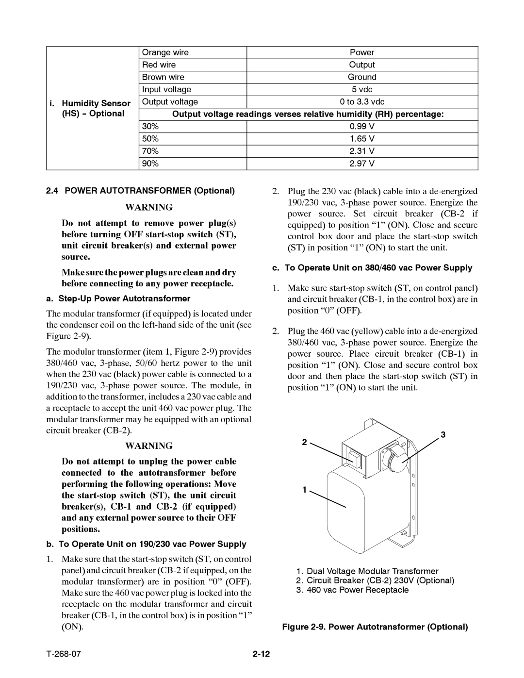
The modular transformer (if equipped) is located under the condenser coil on the left-hand side of the unit (see Figure 2-9).

The modular transformer (item 1, Figure 2-9) provides 380/460 vac, 3-phase, 50/60 hertz power to the unit when the 230 vac (black) power cable is connected to a 190/230 vac, 3-phase power source. The module, in addition to the transformer, includes a 230 vac cable and a receptacle to accept the unit 460 vac power plug. The modular transformer may be equipped with an optional circuit breaker (CB-2).

2.Plug the 230 vac (black) cable into a de-energized 190/230 vac, 3-phase power source. Energize the power source. Set circuit breaker (CB-2 if equipped) to position “1” (ON). Close and secure control box door and place the start-stop switch (ST) in position “1” (ON) to start the unit.

c. To Operate Unit on 380/460 vac Power Supply

1.Make sure start-stop switch (ST, on control panel) and circuit breaker (CB-1, in the control box) are in position “0” (OFF).

2.Plug the 460 vac (yellow) cable into a de-energized 380/460 vac, 3-phase power source. Energize the power source. Place circuit breaker (CB-1) in position “1” (ON). Close and secure control box door and then place the start-stop switch (ST) in position “1” (ON) to start the unit.

WARNING

Do not attempt to unplug the power cable connected to the autotransformer before performing the following operations: Move the start-stop switch (ST), the unit circuit breaker(s), CB-1 and CB-2 (if equipped) and any external power source to their OFF positions.

b. To Operate Unit on 190/230 vac Power Supply

2

1

3

1.Make sure that the start-stop switch (ST, on control panel) and circuit breaker (CB-2 if equipped, on the modular transformer) are in position “0” (OFF). Make sure the 460 vac power plug is locked into the receptacle on the modular transformer and circuit breaker (CB-1, in the control box) is in position “1” (ON).

1.Dual Voltage Modular Transformer

2.Circuit Breaker (CB-2) 230V (Optional)

3.460 vac Power Receptacle

Figure 2-9. Power Autotransformer (Optional)

T-268-07

2-12

Page 31
Image 31
Carrier 69NT40-511-199, 69NT40-521 manual Humidity Sensor, Power Autotransformer Optional, Step-Up Power Autotransformer