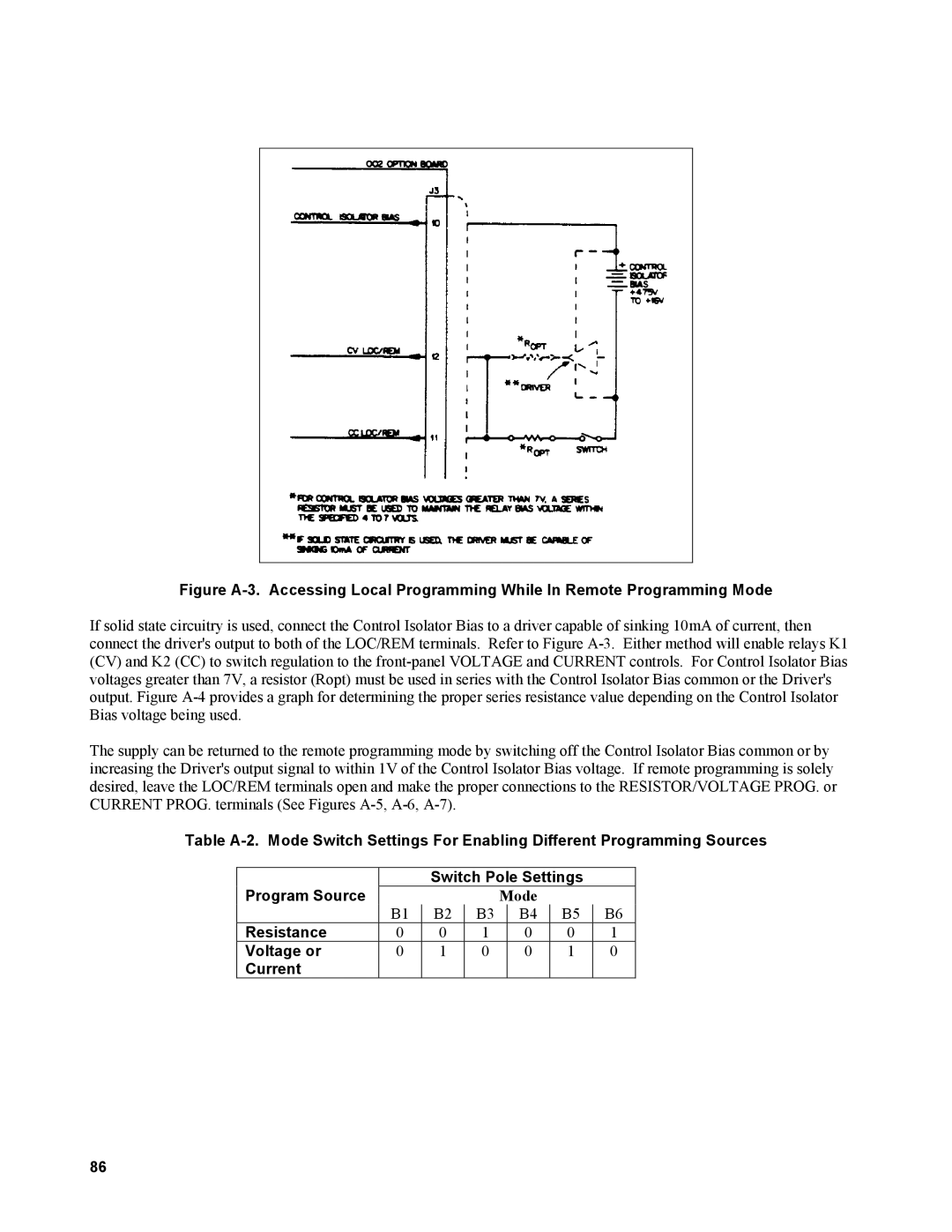
Figure A-3. Accessing Local Programming While In Remote Programming Mode
If solid state circuitry is used, connect the Control Isolator Bias to a driver capable of sinking 10mA of current, then connect the driver's output to both of the LOC/REM terminals. Refer to Figure
The supply can be returned to the remote programming mode by switching off the Control Isolator Bias common or by increasing the Driver's output signal to within 1V of the Control Isolator Bias voltage. If remote programming is solely desired, leave the LOC/REM terminals open and make the proper connections to the RESISTOR/VOLTAGE PROG. or CURRENT PROG. terminals (See Figures
Table
Program Source |
| Switch Pole Settings |
| ||||
|
|
| Mode |
|
| ||
| B1 | B2 | B3 |
| B4 | B5 | B6 |
Resistance | 0 | 0 | 1 |
| 0 | 0 | 1 |
Voltage or | 0 | 1 | 0 |
| 0 | 1 | 0 |
Current |
|
|
|
|
|
|
|
86