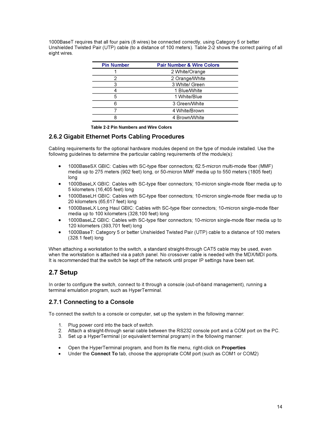
1000BaseT requires that all four pairs (8 wires) be connected correctly, using Category 5 or better Unshielded Twisted Pair (UTP) cable (to a distance of 100 meters). Table
Pin Number | Pair Number & Wire Colors |
1 | 2 White/Orange |
2 | 2 Orange/White |
3 | 3 White/ Green |
4 | 1 Blue/White |
5 | 1 White/Blue |
6 | 3 Green/White |
7 | 4 White/Brown |
8 | 4 Brown/White |
Table
2.6.2 Gigabit Ethernet Ports Cabling Procedures
Cabling requirements for the optional hardware modules depend on the type of module installed. Use the following guidelines to determine the particular cabling requirements of the module(s):
•1000BaseSX GBIC: Cables with
•1000BaseLX GBIC: Cables with
•1000BaseLH GBIC: Cables with
•1000BaseLX Long Haul GBIC: Cables with
•1000BaseLZ GBIC: Cables with
•1000BaseT: Category 5 or better Unshielded Twisted Pair (UTP) cable to a distance of 100 meters (328.1 feet) long
When attaching a workstation to the switch, a standard
2.7 Setup
In order to configure the switch, connect to it through a console
2.7.1 Connecting to a Console
To connect the switch to a console or computer, set up the system in the following manner:
1.Plug power cord into the back of switch.
2.Attach a
3.Set up a HyperTerminal (or equivalent terminal program) in the following manner:
•Open the HyperTerminal program, and from its file menu,
•Under the Connect To tab, choose the appropriate COM port (such as COM1 or COM2)
14