2.3.2 Removing a GBIC
Caution: GBIC 1000T modules run hot under normal operating conditions. When it has been removed from the system, place it on a
Note: Unnecessary removals/insertions of a GBIC module will lead to premature failure of the GBIC connector. The rated duty cycle for a GBIC module is 100 to 500 removals/insertions.
Follow the steps below to remove a GBIC interface from a Gigabit Ethernet module:
1.Disconnect the cable from the GBIC module.
2.Release the GBIC from the slot by simultaneously squeezing the locking tabs on both sides of the GBIC.
3.Slide the GBIC out of the slot.
4.Fiber GBIC modules: Install the rubber plugs in the GBIC optical bores, and place the GBIC in protective packaging.
2.3.3 GBIC Care and Handling
Follow these GBIC maintenance guidelines:
•GBICs are
•Fiber GBIC modules are very sensitive to dust and contaminants. When they are not connected to a
•The ferrules of the optical connectors may pick up debris that can obstruct the optical bore. Use an alcohol swab or equivalent to clean the ferrules of the optical connector
2.4Installing the Optional Emergency Power Supply
To ensure increased reliability for
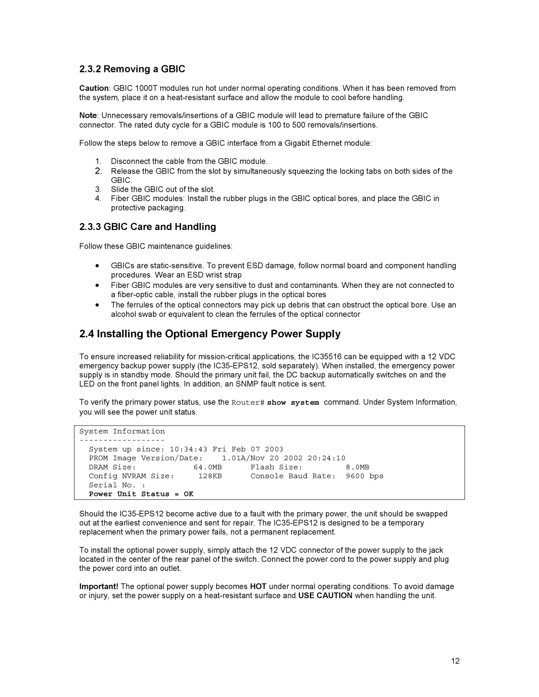
To verify the primary power status, use the Router# show system command. Under System Information, you will see the power unit status.
System | Information |
|
|
|
|
|
|
|
| ||
System up since: 10:34:43 Fri Feb 07 2003 |
|
| |||
PROM | Image Version/Date: | 1.01A/Nov 20 2002 | 20:24:10 |
| |
DRAM | Size: | 64.0MB | Flash Size: |
| 8.0MB |
Config NVRAM Size: | 128KB | Console Baud Rate: | 9600 bps | ||
Serial No. : |
|
|
|
| |
Power Unit Status = OK |
|
|
|
| |
|
|
|
|
|
|
Should the
To install the optional power supply, simply attach the 12 VDC connector of the power supply to the jack located in the center of the rear panel of the switch. Connect the power cord to the power supply and plug the power cord into an outlet.
Important! The optional power supply becomes HOT under normal operating conditions. To avoid damage or injury, set the power supply on a
12