CAUTION: If it is necessary to change the time of the first test ![]() )
)
6. | The red LED (DS1) on the Digital communicator should | |
| be blinking to show normal operation. The LED will not | |
| light if there is no DC power. A steady LED means the | |
| Watchdog circuit has detected a processor or memory | |
| problem. Reset the watchdog with the AT&T Model | |
| 8710 Digital communicator Programmer or AT&T Model | |
| 8711 Remote Programming Package. | |
7. | Connect terminal to earth ground. Use a minimum 14GA | |
| wire. The wire run should be as short and straight as | |
| possible. Sharp angles in the wiring run reduce the | |
| effectiveness of the ground. A good earth ground is | |
| essential for phone line lightning protection. | |
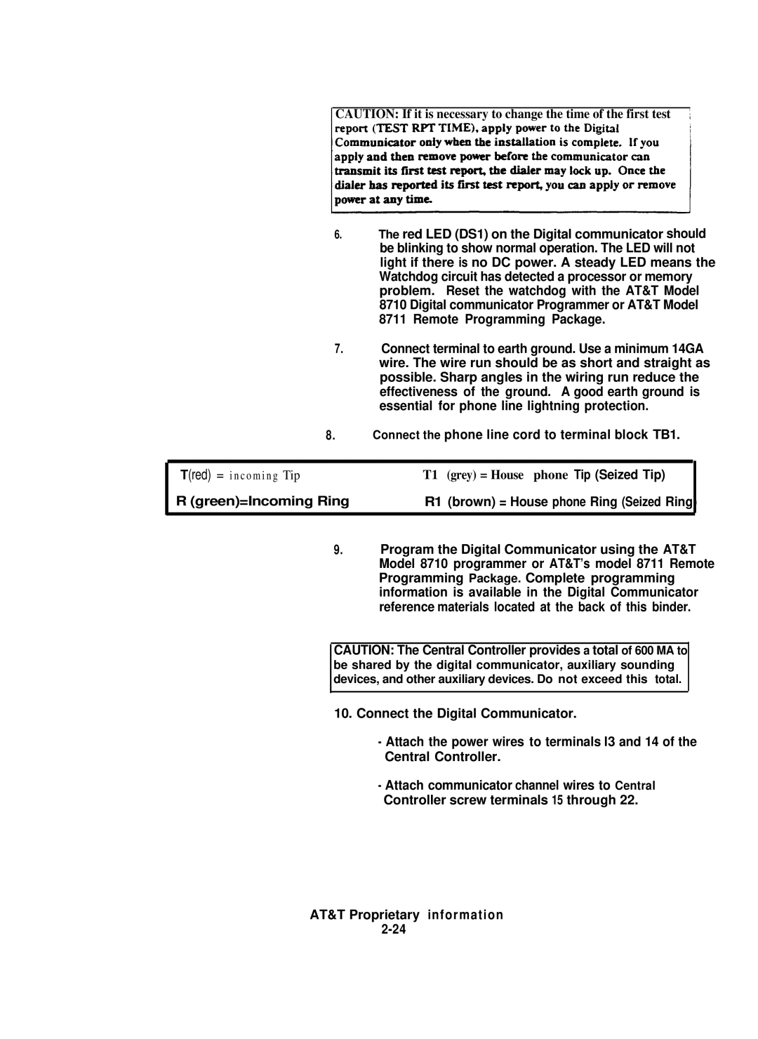
8. | Connect the phone line cord to terminal block TB1. | |
|
|
|
T(red) = i n c o m i n g Tip | T1 (grey) = House phone Tip (Seized Tip) |
|
R (green)=Incoming Ring | R1 (brown) = House phone Ring (Seized Ring) |
|
|
|
|
9. | Program the Digital Communicator using the AT&T | |
| Model 8710 programmer or AT&T’s model 8711 Remote | |
Programming Package. Complete programming information is available in the Digital Communicator reference materials located at the back of this binder.
CAUTION: The Central Controller provides a total of 600 MA to be shared by the digital communicator, auxiliary sounding devices, and other auxiliary devices. Do not exceed this total.
10.Connect the Digital Communicator.
-Attach the power wires to terminals l3 and 14 of the Central Controller.
-Attach communicator channel wires to Central Controller screw terminals 15 through 22.
