RCP120 Installation
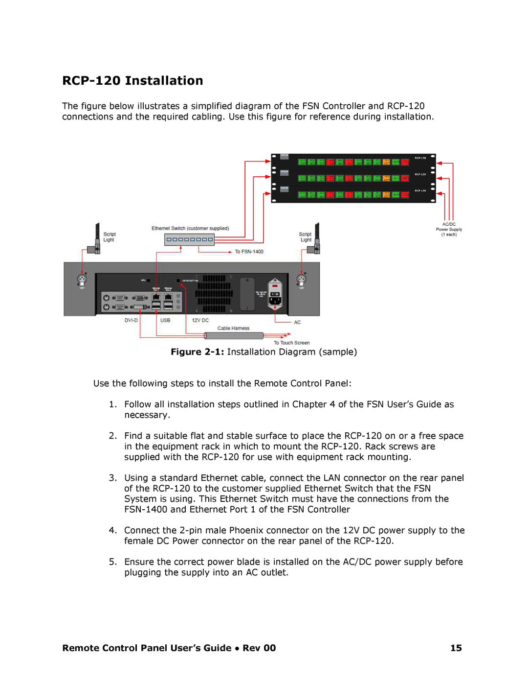
The figure below illustrates a simplified diagram of the FSN Controller and RCP120 connections and the required cabling. Use this figure for reference during installation.
Figure 21: Installation Diagram (sample)
Use the following steps to install the Remote Control Panel:
1.Follow all installation steps outlined in Chapter 4 of the FSN User’s Guide as necessary.
2.Find a suitable flat and stable surface to place the RCP120 on or a free space in the equipment rack in which to mount the RCP120 . Rack screws are supplied with the RCP120 for use with equipment ra ck mounting.
3.Using a standard Ethernet cable, connect the LAN connector on the rear panel of the RCP120 to the customer supplied Ethernet Sw itch that the FSN System is using. This Ethernet Switch must have the connections from the FSN1400 and Ethernet Port 1 of the FSN Controller
4.Connect the 2pin male Phoenix connector on the 12V DC power supply to the female DC Power connector on the rear panel of the RCP120.
5.Ensure the correct power blade is installed on the AC/DC power supply before plugging the supply into an AC outlet.
Remote Control Panel User’s Guide ● Rev 00 | 15 |