Working with the RCP120
When using the RCP120 to control Aux Outputs, the panel will go through different stages during setup as it becomes ready to use. The following illustrations show these stages during a typical configuration session.
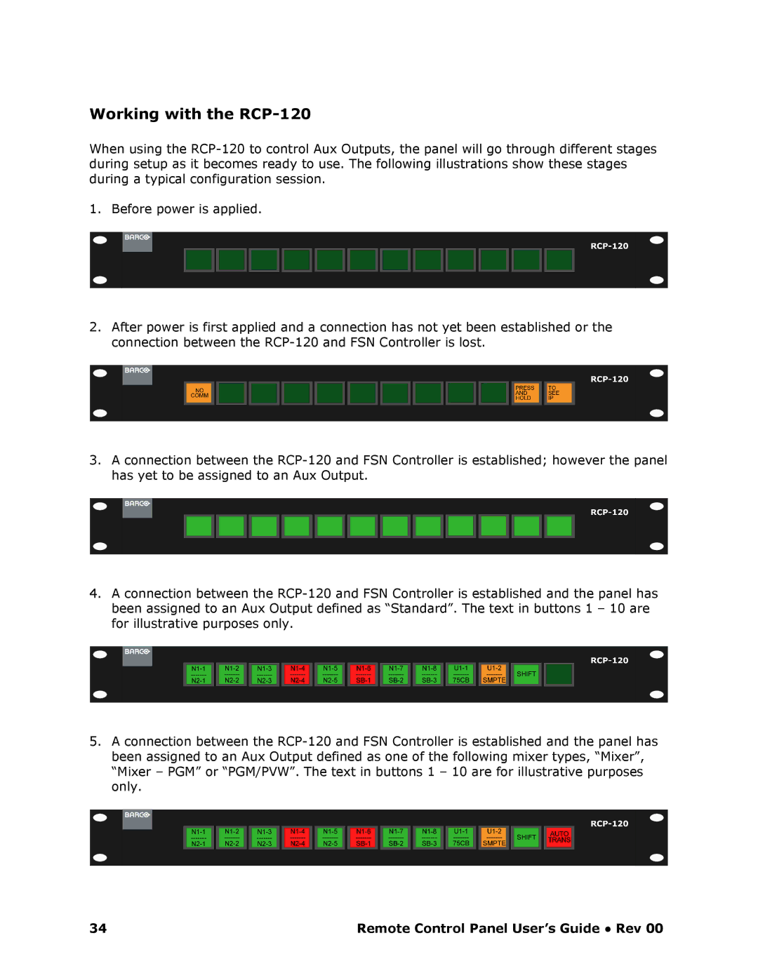
1. Before power is applied.
2.After power is first applied and a connection has not yet been established or the connection between the RCP120 and FSN Controller i s lost.
3.A connection between the RCP120 and FSN Controller is established; however the panel has yet to be assigned to an Aux Output.
4.A connection between the RCP120 and FSN Controller is established and the panel has been assigned to an Aux Output defined as “Standard”. The text in buttons 1 – 10 are for illustrative purposes only.
5.A connection between the RCP120 and FSN Controller is established and the panel has been assigned to an Aux Output defined as one of the following mixer types, “Mixer”, “Mixer – PGM” or “PGM/PVW”. The text in buttons 1 – 10 are for illustrative purposes only.
34 | Remote Control Panel User’s Guide ● Rev 00 |