a.Troubleshoot the network setup/configuration concerning the RCP120 in question and when resolved, press the Discover Remote Panels button to reconnect the panel to the FSN Controller. When the RCP120 has connected to the Controller, the status will change from Red, to Yellow or Green, depending on the Aux assignment state.
b.If the RCP120 has been intentionally disconnected from the FSN network and the operator wishes to update the table so this device no longer shows, press the Discover Remote Panels button. Any devices not found that were listed in the table will be removed from the table after the discovery process is complete.
Controlling an Aux Output with the RCP120
Controlling a “Standard” Aux Output
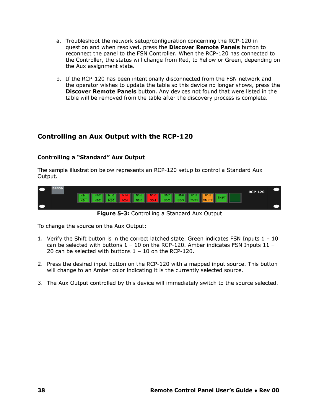
The sample illustration below represents an RCP120 setup to control a Standard Aux Output.
Figure 53: Controlling a Standard Aux Output
To change the source on the Aux Output:
1.Verify the Shift button is in the correct latched state. Green indicates FSN Inputs 1 – 10 can be selected with buttons 1 – 10 on the RCP120. Amber indicates FSN Inputs 11 – 20 can be selected with buttons 1 – 10 on the RCP1 20.
2.Press the desired input button on the RCP120 with a mapped input source. This button will change to an Amber color indicating it is the currently selected source.
3.The Aux Output controlled by this device will immediately switch to the source selected.
38 | Remote Control Panel User’s Guide ● Rev 00 |