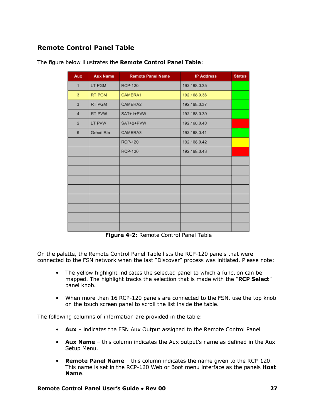
Remote Control Panel Table
The figure below illustrates the Remote Control Panel Table:
Figure 42: Remote Control Panel Table
On the palette, the Remote Control Panel Table lists the RCP120 panels that were connected to the FSN network when the last “Discover” process was initiated. Please note:
∙The yellow highlight indicates the selected panel to which a function can be mapped. The highlight tracks the selection that is made with the “RCP Select” panel knob.
∙When more than 16 RCP120 panels are connected to t he FSN, use the top knob on the touch screen panel to scroll the list inside the table.
The following columns of information are provided in the table:
∙Aux – indicates the FSN Aux Output assigned to the Remote Control Panel
∙Aux Name – this column indicates the Aux output’s name as defined in the Aux Setup Menu.
∙Remote Panel Name – this column indicates the name given to the RCP1 20. This name is set in the RCP120 Web or Boot menu in terface as the panels Host Name.
Remote Control Panel User’s Guide ● Rev 00 | 27 |